


Requirement: A series of numbers needs to be generated which references the pattern instance count.
Solution: Linear Pattern with Instances to vary
Workflow for Part level:
1. Draw the reference lines on the part and dimension the reference line.
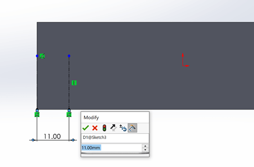
Make note of the dimension name.
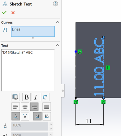
2. Use Sketch text command and with the line as reference start typing the value required.
To achieve the incremental numbering, we need to map the text directly. The name of the dimension (“D1@Sketch3”) needs to be typed manually.
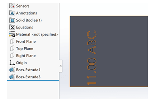
3. Use the Boss-Extrude or Cut-Extrude as per requirement.
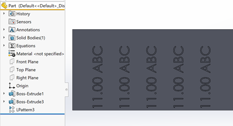
4. Use the Linear Pattern command and patter the feature with text in the required direction.
5. To make the numbering sequential, edit the linear pattern and check the box for Instance to Vary.
Under “Choose feature to vary in Direction1” select the dimension which was created in Step 1.
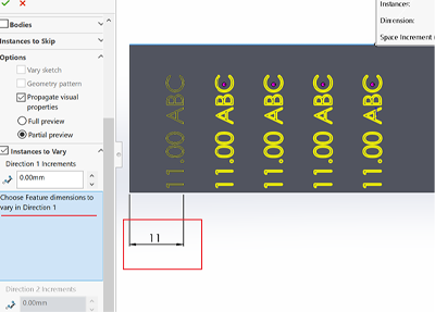
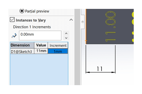
Once the dimension is selected it will be visible under the Value column (11mm in my casestudy) and the required increment needs to be filled under Increment column.
Workflow for Assembly level:
1. Create a new part (Insert > Component > New part) in the required assembly.
2. Edit the newly created part and start creating new feature at the required location.
3. Follow the steps 1-5 mentioned above to achieve the incremental update of values.
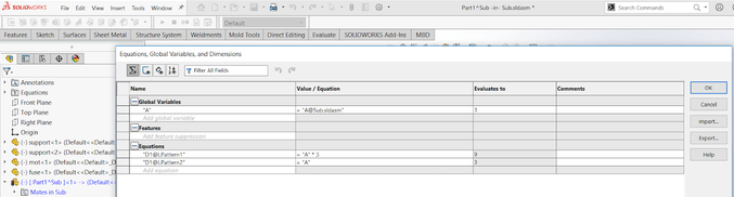
To link the equation for automatic update of patterns:
4. Tools>Equations – Create a new variable for this new part and under “Values/Expressions” you need to map it to the assembly equation directly.
The syntax to link an assembly variable to part level is – “Variablename@Assemblyname.sldasm” For this part, the syntax is “A@Sub.sldasm”.
Refer the image for further understanding.
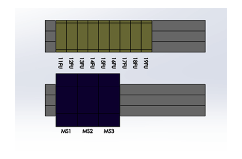
5. When the parameters are modified the motor, starter and the label components will update automatically with reference to the equations provided.
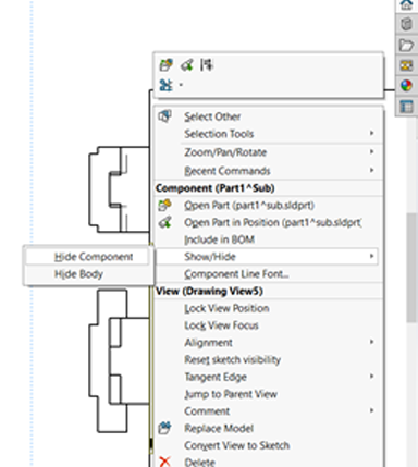
To avoid the new components to reflect in drawing:
6. In the drawing sheets after the views are created, if the labelled component is not required then it can be hidden by selecting the component over the sheet or from the feature tree > right click > Show/Hide > Hide Component.
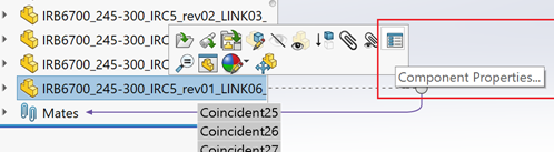
To avoid the new components to reflect in BOM:
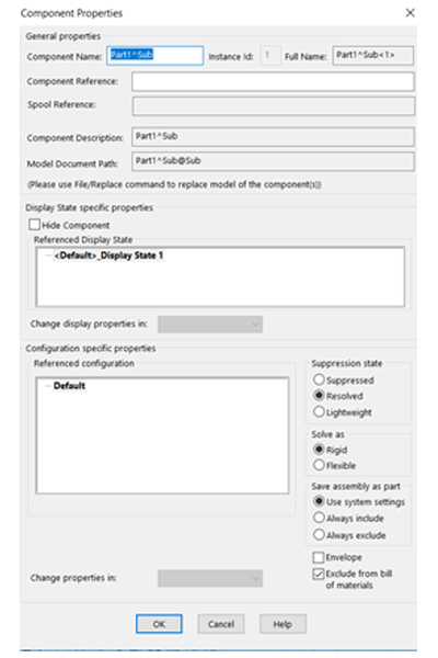
7. Left / Right click on the component in the assembly feature tree and select the option “Component Properties” and check the box “Exclude from bill of material”.
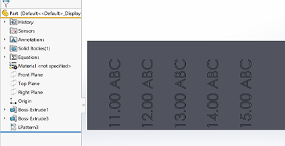
Explanation: The “Instances to Vary” option is usually used to modify a dimension from pattern instance to pattern instance. In our case, we will use it to increment our dummy dimension. Because we set the text value to that very same dummy dimension, it will in fact change the text value of each repetition!!!
We Urge You To Call Us For Any Doubts & Clarifications That You May Have. We Are Eager to Talk To You
Call Us: +91 7406663589

 (2 votes, average: 3.00 out of 5)
#365/8, Ground Floor, "Hasmitha Avenue", 16th Main, 4th T Block East, Jayanagar, 4th T Block East, Pattabhirama Nagar, Jayanagar, Bengaluru, Karnataka 560041
Rated 4.7/5 with a total of 62 reviews
"CARAX" Building 4th Floor, 105/1/1/4, Next to Radha Hotel, Pune-Mumbai Xpress Way,Baner,Pune 411045
Rated 4.7/5 with a total of 17 reviews
1002, LODHA Supremus, I-Think Techno Campus,Kanjurmarg EAST - MUMBAI, MH, India – 400042.
Rated 5/5 with a total of 51 reviews
508, Shiti Ratna Complex, Panchwati Cross Road, Ahmedabad-380006
Rated 4.1/5 with a total of 7 reviews
Kanda's Villa, II Floor, AE Block,3362 R, 8th Street, Anna Nagar, Chennai, Tamil Nadu 600040
Rated 4.6/5 with a total of 16 reviews
Flat no F1, first floor, Nakhate corner, Eknath rang mandir road,New Usmanpura, Aurangabad, 431005.
A-101, 1st Floor, The Hub Complex, opp. Shete Hospital, Mahatma Nagar, Parijat Nagar, Nashik, Maharashtra 422005.
Level 7, Octave 3B Salarpuria Sattva Knowledge City, Inorbit Mall Road, Raidurg Village, Hi-tech City, Hyderabad, Telangana - 500081, India