


A Topology study performs nonparametric topology optimization of parts. Starting with a maximum design space (which represents the maximum allowed size for a component) and considering all applied loads, fixtures, and manufacturing constraints, the topology optimization seeks a new material layout, simplifies structural topology investigations with a goal-driven approach to mathematically alter the stiffness of the meshed geometry. Assuming linear static loading designers and engineers specify target mass reduction and the delivered results show which regions of a component can be removed within the boundaries of the maximum allowed geometry without compromising the component stiffness, by redistributing the material with all the required mechanical and manufacturing requirements satisfied.
The SOLIDWORKS Simulation Topology Study included in the SOLIDWORKS Simulation Professional version
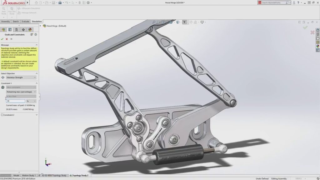
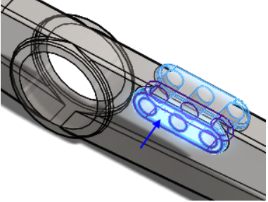
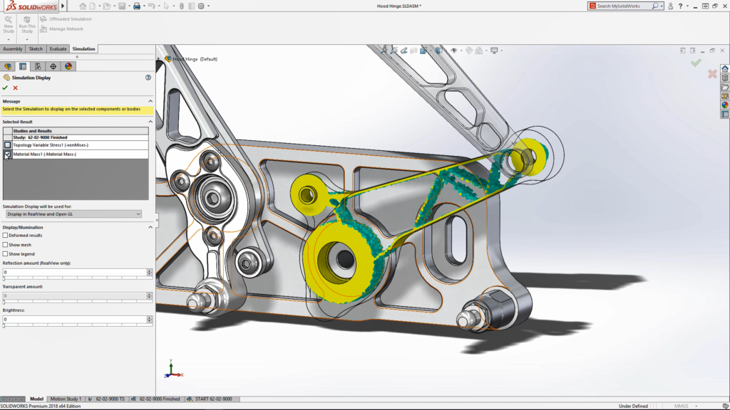
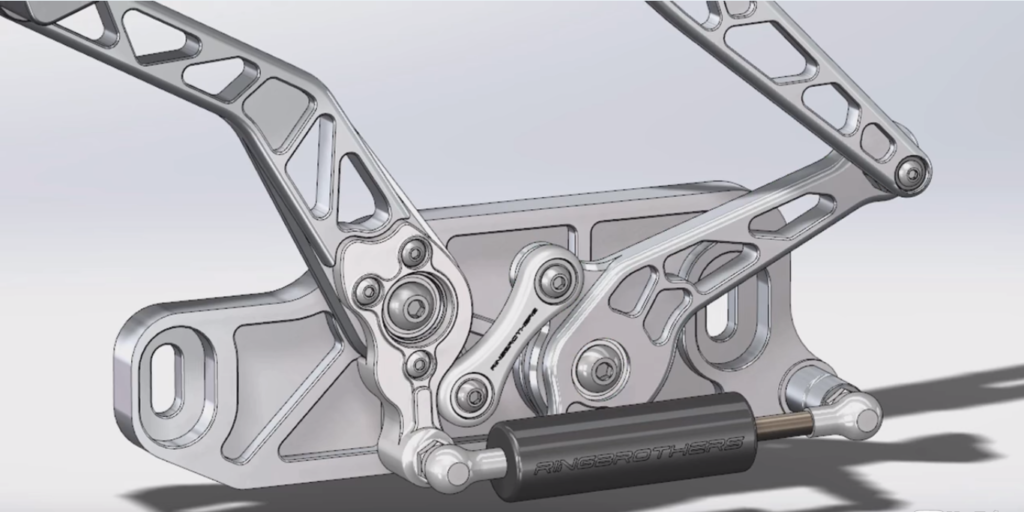
Consider the below Example wherein we can optimize the part of a car hood opening mechanism, as shown in the image below in blue, in terms of strength and weight (image courtesy of Ring Brothers LLC).
With a Topology study, we can define a design goal stating
Thereby making the design proposal reached by the iterative optimization process should fulfill all structural and manufacturing requirements predefined.
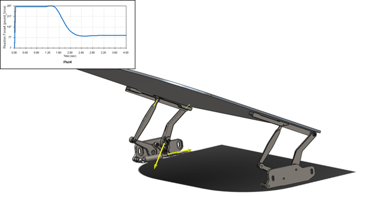
By carrying out a motion analysis on the assembly, the loads at the link connection points can be calculated and transferred to the part for analysis. The loads on the blue link are shown by the size of the yellow arrows in the image below and the maximum load on the gas strut.
It is always best suggested to complete a static analysis to the part prior to running a topology study to ensure that the loads applied do not result in stresses that are beyond the components yield strength.
Creating a Topology Study is pretty much similar a static study; the materials, loads and restraints are the same.
The difference is the only 2 new inputs:
In a Topology study tree, right-click Goals and Constraints, and select one of the three optimization goals:
Constraints limit the design space solutions by enforcing the percentage of mass that can be eliminated to be under a certain value,
;
Set the targeted mass that the part will be reduced by during optimization. Select one of the following:
The optimization algorithm will attempt to reach the targeted mass reduction for the final shape through an iterative process.
Sets the upper limit for the selected displacement component. In Component, select the desired displacement variable. Select one of the following:
Select one of the following for a reference vertex location for the displacement constraint:
The optimization process creates a material layout that satisfies the optimization goal and any geometric constraints you define. However, the design may be impossible to create using standard manufacturing techniques, such as casting and forging.
Applying proper geometric controls prevents the formation of undercuts and hollow parts. Manufacturing restrictions ensure that the optimized shape can be extracted from a mold, or can be stampable with a tool and die.
We can freeze regions of your model that are contacting other parts, such as regions that are used to support the model and regions that form bearing surfaces. These regions do not participate in a topology optimization and remain unchanged.
We can add de-mold controls to ensure that the optimized design is manufacturable and can be extracted from a mold. Application of geometric controls prevents the formation of undercuts and cavities and ensures that the optimized shape can be extracted from a mold.
The below are the 3 possibilities in specifying the directions
Symmetry control forces the optimized design to be symmetric about a specified plane. You can enforce a half, quarter, or one-eighth planar symmetry for an optimized design.
Apply member size restrictions for a topology optimization that prohibits the creation of very thin or very thick regions that may be difficult to manufacture. The final optimized design adheres to the member size restrictions you specify.
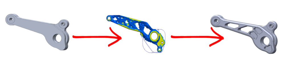
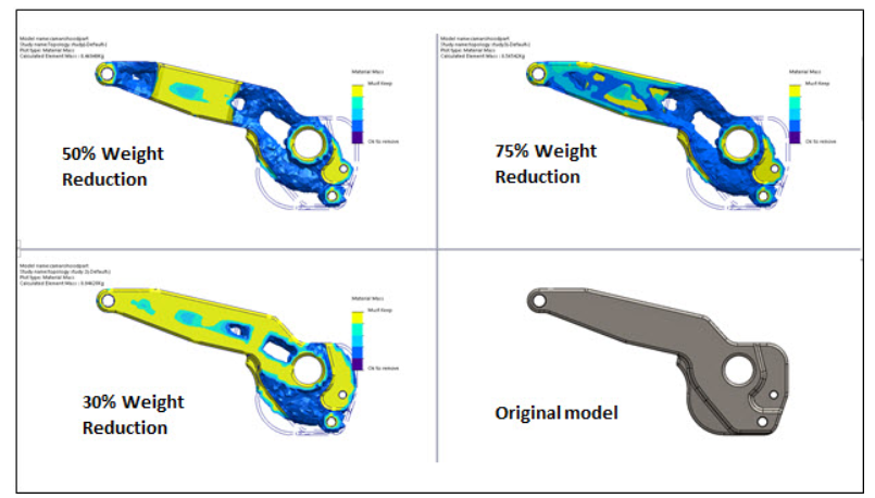
Once you have your topology results
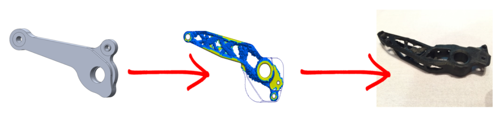
Optimization proposal for SolidWorks Topology Optimization
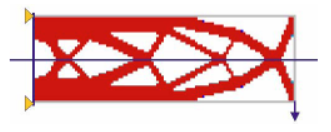
Optimized Geometry
We Urge You To Call Us For Any Doubts & Clarifications That You May Have. We Are Eager to Talk To You
Call Us: +91 7406663589
 (No Ratings Yet)
#365/8, Ground Floor, "Hasmitha Avenue", 16th Main, 4th T Block East, Jayanagar, 4th T Block East, Pattabhirama Nagar, Jayanagar, Bengaluru, Karnataka 560041
Rated 4.7/5 with a total of 62 reviews
"CARAX" Building 4th Floor, 105/1/1/4, Next to Radha Hotel, Pune-Mumbai Xpress Way,Baner,Pune 411045
Rated 4.7/5 with a total of 17 reviews
1002, LODHA Supremus, I-Think Techno Campus,Kanjurmarg EAST - MUMBAI, MH, India – 400042.
Rated 5/5 with a total of 51 reviews
508, Shiti Ratna Complex, Panchwati Cross Road, Ahmedabad-380006
Rated 4.1/5 with a total of 7 reviews
Kanda's Villa, II Floor, AE Block,3362 R, 8th Street, Anna Nagar, Chennai, Tamil Nadu 600040
Rated 4.6/5 with a total of 16 reviews
Flat no F1, first floor, Nakhate corner, Eknath rang mandir road,New Usmanpura, Aurangabad, 431005.
A-101, 1st Floor, The Hub Complex, opp. Shete Hospital, Mahatma Nagar, Parijat Nagar, Nashik, Maharashtra 422005.
Level 7, Octave 3B Salarpuria Sattva Knowledge City, Inorbit Mall Road, Raidurg Village, Hi-tech City, Hyderabad, Telangana - 500081, India