Today plastic parts are found in almost all industrial applications ranging from electronics, automobile components, medical devices & children’s toys. The list goes on… Majority of these plastic parts are made using injection molding. This process is fairly complex taking into consideration the material selection, fill time, pressure and temperature to be maintained in the mold, mold opening time, etc. Designers are often left with questions that they would like to get the answers to before making the initial costly mold. This is where a mold flow analysis tool like SOLIDWORKS Plastics comes into picture.
SOLIDWORKS Plastics Standard is a world class mold cavity analysis software that contains analysis tools to validate and optimize plastic part design for the injection molding process. It can be specifically used by plastic part designers to predict the part performance during the injection molding process. The software can be bought as an add-on package to SOLIDWORKS CAD and integrates seamlessly within the same CAD window. This makes it easy to learn and gives the designer the capability to analyze and modify the design if needed.
What is the analysis method?
SOLIDWORKS Plastics uses the Finite Volume Method to simulate the plastic flow and heat transfer during the filling, packing and cooling stages. While for the Warping analysis, the Finite Element Analysis (FEA) approach is used.
What are the different features that I get in Plastics Standard Package?
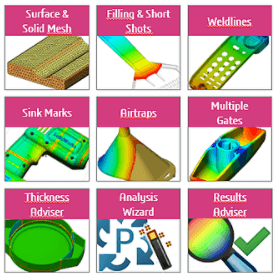
SOLIDWORKS Plastics Standard features
How does one perform the analysis? And what are the steps to be taken?
To begin a new analysis with SW Plastics, simply click on the New Study tab and give the study a suitable name. For beginners, a Getting Started Guide helps set up an analysis.
![]()
Under Boundary Conditions, Injection location can be specified manually, or we can let the software decide the gate location automatically depending on the part geometry.
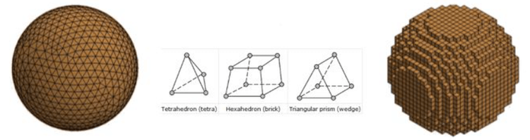
Mesh Elements in SW Plastics
Above fig shows different types of mesh elements available in SW Plastics.
The next step is to discretize the model or mesh modelling. SW Plastics offers 2 type of meshing. Surface mesh and Solid mesh. Both can be setup manually as well as automatically. Surface mesh is generally used for thin wall components or to quickly run a fill analysis of a large dimension part just to see if the part cavity is being filled or not. A surface mesh can be (or rather is) converted into a solid mesh for further analysis. A solid mesh gives us more accurate results. The different types of solid elements that the software offers are the Tetrahedral element (Tet), Hexahedral element (Hex or brick), and Hybrid (a mix of both Tet for internal volume and Hex on the boundary). On meshing the model, the software also shows the summary of mesh with values of element and node count, aspect ratio, skewness ratio, etc. It also tells if the model is ‘watertight’ or not. If the CAD model is imported from another software, there might be chances that that surfaces are broken or there are gaps in between them. (SOLIDWORKS offers diagnostic features to create a watertight geometry before performing an analysis).
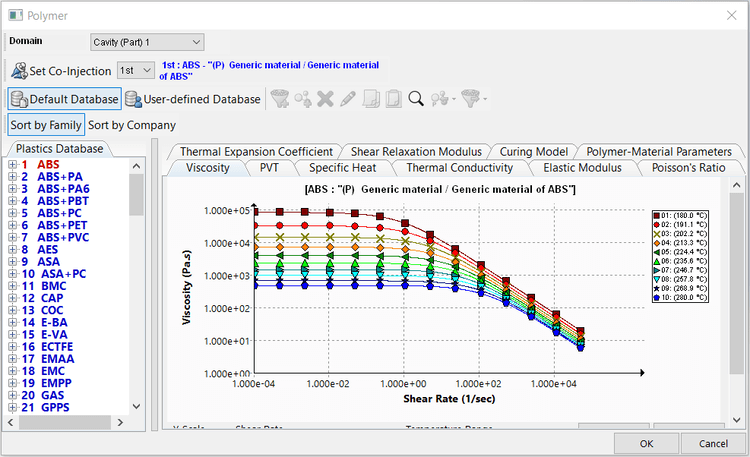
Polymer Library
Above fig shows polymer library.
Polymer selection is easy with an inbuilt fully customizable polymer library. This includes over 3000 polymers which can be sorted by company or by family. Once the polymer is applied, the software takes the polymer parameters such as melt temperature automatically when running the analysis. Also, the recently used polymers are readily available next time you want to apply them.
Now we can input the boundary conditions. For Plastics Standard package users, only Fill Settings are visible. Various parameters like fill time, melt temperature, mold temperature injection pressure limit, etc. are taken by the software automatically. You also can manually change them.
Once all the parameters are set, click on Run Flow results. The analysis manager starts showing you the percentage volume filled. There is also an option to show the filling in real time on the CAD model. This analysis manager window can be minimized and will keep on working in the background. When the results are ready, various results will be showcased under Fill Time Results. Also, a Results Advisor opens on the right-hand side of SOLIDWORKS.
How much time does it take to run a simulation?
This is a common question and there is no straightforward answer to it. Run time is dependent on number of factors. One of them being the mesh. The higher the number of elements, more the time required to run the simulation. There is always a tradeoff between these two. But an experienced designer might know that if the mesh quality is good and the aspect ratio is within industry acceptable limit, no further refinement in mesh would be required.
What are the available results after the flow analysis is complete?
Analysis predicts how the material flows in the mold cavity. Results show fill time, pressure distribution, indicate short shots, weld lines, and air traps. You get to see a neat fill analysis animation too. Air traps are shown on part as purple-colored bubbles. Weld lines can be seen in color as the part appears transparent to highlight their position in the plastic part. We can also see the vector orientation when the option of ‘velocity vector at end of fill’ is enabled. ‘Clipping plane mode’ and ‘Iso-surface mode’ are available to inspect the part after the analysis is complete. All the results and plots can be exported to eDrawings for viewing and further sharing with other departments. At any time, the results adviser can be launched from the same menu.
At the end, a report is automatically generated in Microsoft Word and Power point. This report accurately captures all the aspects of the analysis (boundary conditions, injection location, fill time, graphs & plots, and even animations).
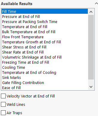
SOLIDWORKS Plastics Standard Available Results
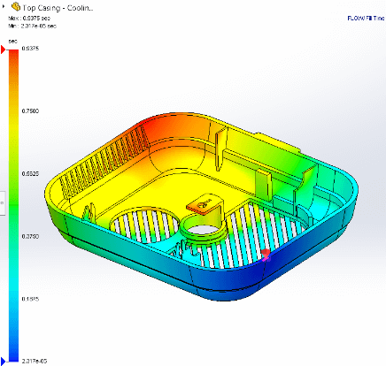
SOLIDWORKS Plastics Standard fill time plot
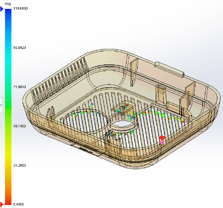
SOLIDWORKS Plastics Standard weld lines
Above fig. shows available results, fill time plot & weld lines.
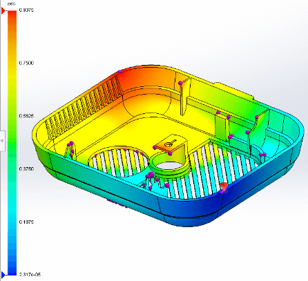
SOLIDWORKS Plastics Standard air traps along with injection location in red color
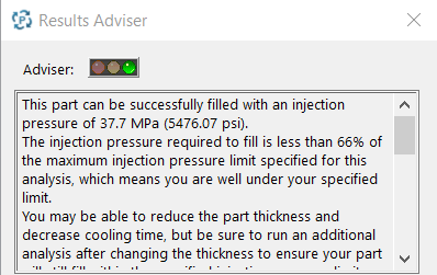
SOLIDWORKS Plastics Standard results adviser
Above fig. shows air traps along with injection location in red color and the results adviser.
The results adviser gives color indication like a traffic signal. Green color indicates the part can be filled successfully while Orange indicates that the part can be filled but with certain difficulty. Red color however indicates either a short shot or change in pressure or fill time.
We Urge You To Call Us For Any Doubts & Clarifications That You May Have. We Are Eager to Talk To You
Call Us: +91 7406663589
 (No Ratings Yet)
Brigade Deccan Heights, 42, 14th Floor, 5th Mile, Tumkur Rd, Yeshwanthpur Industrial Area, Phase 1, Yeswanthpur, Bengaluru, Karnataka 560022
Rated 4.7/5 with a total of 62 reviews
#1120, 11th Floor, Solitaire business Hub - Baner, Balewadi High Street, Baner, Pune-411045
Rated 4.7/5 with a total of 17 reviews
801, 8th Floor, LODHA Supremus, I-Think Techno Campus,Kanjurmarg EAST - MUMBAI, MH, India – 400042.
Rated 5/5 with a total of 51 reviews
501, 5th Floor, Connekt Coworking Space, Gala Argos, Netaji Rd, Ellisbridge, Ahmedabad, Gujarat 380006
Rated 4.1/5 with a total of 7 reviews
Best Engineering Aids & Consultancies Pvt. Ltd. No 306, Karunaa Conclave, 3rd Floor, AD Block, Shanthi Colony, Anna Nagar, Chennai - 600040
Rated 4.6/5 with a total of 16 reviews
Flat no F1, first floor, Nakhate corner, Eknath rang mandir road,New Usmanpura, Aurangabad, 431005.
A-101, 1st Floor, The Hub Complex, opp. Shete Hospital, Mahatma Nagar, Parijat Nagar, Nashik, Maharashtra 422005.
Best Engineering Aids & Consultancies Pvt Ltd (BEACON) Wellwork Workspaces, L1 - 1017A,B, Lower Ground Floor,Vasavi MPM Grand, Ameerpet, Hyderabad, Telangana 500073
2nd floor, Mokha Tower, Plot No.169, Mankapur Ring Rd, Trimurti Nagar, Nagpur, Maharashtra 440022