
Easy to use and powerful P&ID drawing tools from SolidPlant are the best in its class of P&ID software available today. With hardly any additional training required, you will be able to instantly use SolidPlant P&ID, the same way you use your existing CAD package every day. Not only do we offer a full library of P&ID symbols, we put a high level of intelligence in your drawing. Bi-direction with SolidPlant3D will make your design workflow much smoother and more accurate.
SolidPlant P&ID will make sure your P&ID drawing is intelligent and connected.
In SolidPlant P&ID it’s very easy to save your assemblies into the database and replace them in any of your drawings at any time. Whenever you’re working on a project that has a lot of identical assemblies, this feature will save you many hours. With the function ‘Block Assembly’ you can replace a saved assembly as many times as you want. After placing the assemblies, you can assign the tags. The system detects the existing tags and will suggest the next tag in sequential order. As all the data is copied, like the size of the components, only the tags need to be updated.
In SolidPlant P&ID, it’s possible to attach supporting documents to your drawing. With the ‘Attach Object’ function, you can attach an object to any part of your drawing. Whether it’s equipment, a valve, fittings, nozzles, anything is possible. You can attach a wide array of files to your drawing. For example an excel file of a status list, a jpg of a 3D model, a 2D drawing in pdf format, any document that you require.
Whenever you’re working on a big project and your process lines are spread over multiple sheets, SolidPlant P&ID is able to connect them by using off-page connectors. The connectors make sure that the tag data of the outgoing lines will be the same as the incoming lines in the next sheets. Connecting drawings can also be opened directly from the off-page connector. SolidPlant P&ID will make sure your project stays connected.
SolidPlant P&ID allows for a high degree of customization, as we understand that every industry has its own standards. To make this easier, in SolidPlant P&ID you only have to make a custom symbol once to be able to use it in all your projects. It’s really easy to import custom made symbols from one project into another. Every custom symbol is made intelligent like all other standard symbols, meaning that when you attach a process line, a nozzle is automatically placed.
To cater the need of any user who wishes his own style of annotations, SolidPlant P&ID has made it very easy to make your own customized annotations and place them in the drawing. You can create any number of customized fields for equipment, fittings, lines, etc. Different options for text size, fonts, colors and orientation will help you to quickly identify the properties of the items in your drawing. Saved annotations can be changed even after creation and will update all previously placed annotations.
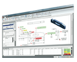
Create, Modify, and Manage Piping and Instrumentation Diagrams with SolidPlant P&ID.
Built on the latest 2D platform, SolidPlant P&ID Interface is easy to use and familiar to designers and engineers, so your design team can start immediately with minimal training. Everyday tasks are streamlined and automated to boost productivity, while component and line information is easily accessed as you work.
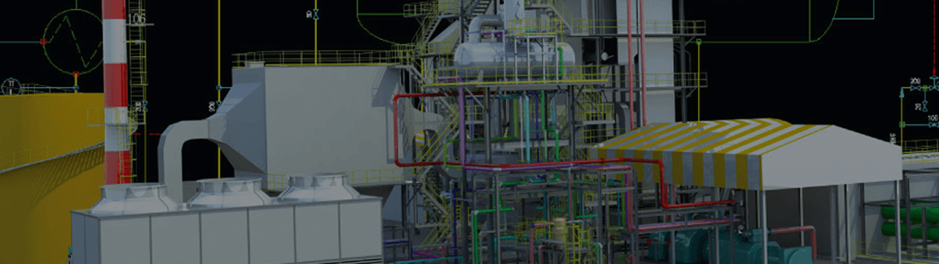
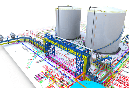
SolidPlant P&ID with SolidPlant 3D makes creating and designing your Project easy and efficient, offering many benefits to EPC’s and Owner Operators.
With simple reporting, editing, sharing, validation, and exchange of design information, SolidPlant P&ID application helps your projects start easier, run better, and finish smarter.
Project Manager
Easily set up projects and preview drawings with straightforward organization and management of DWG files.
Data Manager
Sort and organize underlying P&ID data for easy referencing and see specific information in the context of the drawing.
Dynamic Lines and Components
Lines and components are dynamic with SolidPlant P&ID. Reduce manual breaking and mending of lines with intuitive grip editing and manipulation. Create, move, and snap lines into equipment. Lines automatically break, maintain flow direction, and attach to components that are inserted on, or attached to, the line. When a component is removed, lines mend automatically. Quickly move and snap components with dynamically linked properties and information in place without the burden of manually editing underlying data.
Tagging and Annotations
Easily create, edit, and customize tags and annotations in industry-standard formats. Simply click on the Equipment, lines or component you can manage the tag.
Tagging Register
SolidPlant P&ID is a Database driven engine which maintains a registry of unique tag numbers, whether in single-user mode or a network environment. The system automatically alerts you when duplicate tag numbers are encountered and notifies you of the problem.
Synchronization of P&ID data to SolidPlant3D
Easily report, edit, exchange, and share project engineering information, and know the impact of external data updates for better management. Export data directly to SolidPlant3D. Quickly sort and organize information for easy referencing. Enhanced change management, viewing, and editing functionality help ensure that nothing slips through the cracks.
Export BOM for SolidPlant P&ID
There is a high level of repeated information on a P&ID drawing and with the capabilities of the SolidPlant P&ID Data Manager, speed and accuracy is increased. We can simply cut and paste information from component to component.
Using SolidPlant P&ID software means that you can make the schematics and drawings faster than ever before.Everything you need is included in the software. Being able to create reports means you can make purchasing lists so your suppliers can produce prices for the equipment you need much more quickly. This enables you to deliver your quotations much earlier than you could have had before.
to do more research to improve your product development with SOLIDWORKS!
 Team Autotech India Pvt Ltd.
T3 Energy Services
SIDEL India Pvt. Ltd.
Pressure Control Engineer, T3 Energy Services
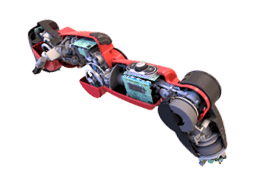
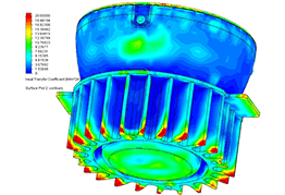
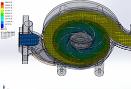
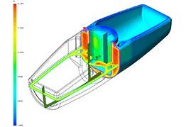
SOLIDWORKS is the best and preferred solution for oil and Gas equipment product design. It has all in one package integration with CAD, Simulation and Flow Analysis. This CAD Operation requires minimum duration of training to get hands on.


#365/8, Ground Floor, "Hasmitha Avenue", 16th Main, 4th T Block East, Jayanagar, 4th T Block East, Pattabhirama Nagar, Jayanagar, Bengaluru, Karnataka 560041
Rated 4.7/5 with a total of 62 reviews
"CARAX" Building 4th Floor, 105/1/1/4, Next to Radha Hotel, Pune-Mumbai Xpress Way,Baner,Pune 411045
Rated 4.7/5 with a total of 17 reviews
1002, LODHA Supremus, I-Think Techno Campus,Kanjurmarg EAST - MUMBAI, MH, India – 400042.
Rated 5/5 with a total of 51 reviews
508, Shiti Ratna Complex, Panchwati Cross Road, Ahmedabad-380006
Rated 4.1/5 with a total of 7 reviews
Kanda's Villa, II Floor, AE Block,3362 R, 8th Street, Anna Nagar, Chennai, Tamil Nadu 600040
Rated 4.6/5 with a total of 16 reviews
Flat no F1, first floor, Nakhate corner, Eknath rang mandir road,New Usmanpura, Aurangabad, 431005.
A-101, 1st Floor, The Hub Complex, opp. Shete Hospital, Mahatma Nagar, Parijat Nagar, Nashik, Maharashtra 422005.
Level 7, Octave 3B Salarpuria Sattva Knowledge City, Inorbit Mall Road, Raidurg Village, Hi-tech City, Hyderabad, Telangana - 500081, India