


DESIGN STUDY:
It is an automated process for studying different types of design scenarios for an assembly / a component. This study is of two modes, Evaluate and Optimization study.
In evaluate mode of study, several geometrical and/or simulation parameters are varied, and the obtained results are then compared with each other or with the benchmark if available, whereas in optimization mode, the user can get an optimized design for your requirements through series of iterations with multiple parameters and constraints such as Stress, Strain, Displacement, Mass etc.,
You can work on several problems by using a design study. You can:
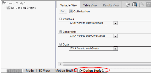
Typical design study tab interface
Variables: The inputs can be Model Dimension, Global Variable, Simulation parameters and Material properties.
Constraints: The inputs can be from Simulation data (Stress, Displacement, Frequency, Temperature, etc.,), Mass Properties, Dimension, Measurement and Costing data.
Goals: There are targets. The inputs for this are same as constraints. This data is required only for Optimization mode design study.
Example for Evaluation Design Study:
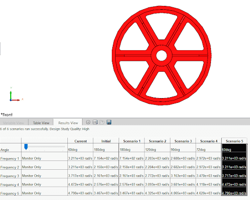
In the following example, the designer wants to understand the natural frequency and modes if there is a change in the geometry. To perform this analysis, the angle between two ribs is varied in a pulley. These angles were provided manually in the variables. For the constraints, the five natural frequencies are considered from the Frequency analysis.
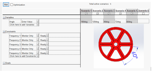
The above picture is the setup for the evaluation design study.
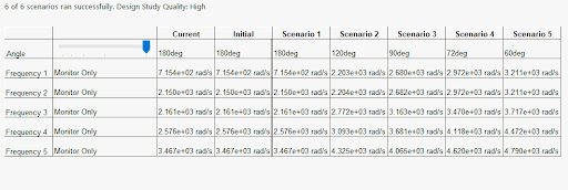
The above picture shows the results view of the study. As the angle is decreased, the natural frequencies are increasing. One of the reasons for the raise in frequency is addition of mass to the pulley as the number of ribs are increased.
In this way, the designer can quickly analyze the various designs in a short duration and can obtain the component design with that design variable. Also, the designer can export these results to Excel in the form of .csv file from SOLIDWORKS Simulation.
Results of Evaluation Design Study:
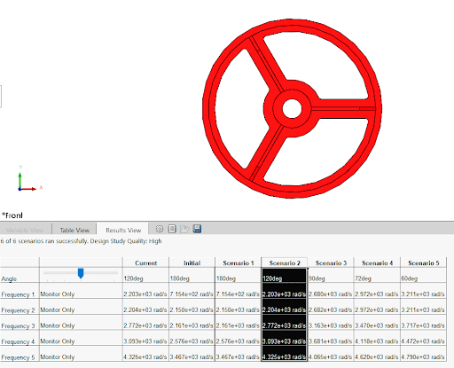
From the above two pictures, it is observed that the one of the Scenarios is selected and the respective design of the component is getting displayed. In one of the figures, the angle is 120 deg and hence, there are three ribs on the pulley whereas the other picture has 6 ribs as the angle stated is 60 deg.
Example for Design Study Optimization:
In this example, the designer is trying to reduce the material volume for a cantilever bracket. To perform this study, the designer has provided with certain constraints and the goal to minimize the material volume.
The constraints are as follows, the maximum resultant displacement is 0.21 mm, maximum stress is 300 MPa and has a frequency range in 260 Hz to 400 Hz, and the goal is set to minimize the volume of the material.
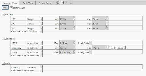
The above picture is the setup for the optimization design study.
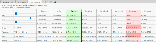
In the results view, the designer will observe three color codes. The red color column indicates that, one of the constraints criteria has been failed. The black color columns indicate that there are no problems with that designs and green color indicates the optimal i.e., optimized design for the given criteria.
The advantage of this study is all these iterations are not only solved but also can be created on one click with this part dimensions for the further work. Also, all these results can be exported to Excel in .csv format for numerical evaluation.
Shape optimization results:
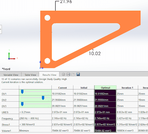
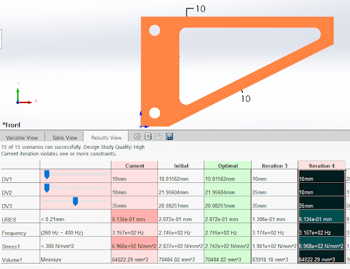
From the above two pictures, it is very clear seen that, in the optimal design the material usage is very minimal and yet provides the performance in all the required design criteria whereas the other design with high material volume has failed in two criteria URES (Resultant displacement) and Stress values.
In this manner, the design study option is very handy for the design engineers and saves lot of time, energy and costs to the designer and organization.
We Urge You To Call Us For Any Doubts & Clarifications That You May Have. We Are Eager to Talk To You
Call Us: +91 7406663589
 (1 votes, average: 5.00 out of 5)
#365/8, Ground Floor, "Hasmitha Avenue", 16th Main, 4th T Block East, Jayanagar, 4th T Block East, Pattabhirama Nagar, Jayanagar, Bengaluru, Karnataka 560041
Rated 4.7/5 with a total of 62 reviews
"CARAX" Building 4th Floor, 105/1/1/4, Next to Radha Hotel, Pune-Mumbai Xpress Way,Baner,Pune 411045
Rated 4.7/5 with a total of 17 reviews
1002, LODHA Supremus, I-Think Techno Campus,Kanjurmarg EAST - MUMBAI, MH, India – 400042.
Rated 5/5 with a total of 51 reviews
508, Shiti Ratna Complex, Panchwati Cross Road, Ahmedabad-380006
Rated 4.1/5 with a total of 7 reviews
Kanda's Villa, II Floor, AE Block,3362 R, 8th Street, Anna Nagar, Chennai, Tamil Nadu 600040
Rated 4.6/5 with a total of 16 reviews
Flat no F1, first floor, Nakhate corner, Eknath rang mandir road,New Usmanpura, Aurangabad, 431005.
A-101, 1st Floor, The Hub Complex, opp. Shete Hospital, Mahatma Nagar, Parijat Nagar, Nashik, Maharashtra 422005.
Level 7, Octave 3B Salarpuria Sattva Knowledge City, Inorbit Mall Road, Raidurg Village, Hi-tech City, Hyderabad, Telangana - 500081, India

pin-up 141 https://azerbaijancuisine.com/# pin up onlayn kazino
pin up az
buying prescription drugs in mexico mexican pharmacy buying prescription drugs in mexico online
mexican drugstore online mexican pharmacy northern doctors reputable mexican pharmacies online
buying prescription drugs in mexico mexican pharmacy mexico pharmacies prescription drugs
https://northern-doctors.org/# best online pharmacies in mexico
mexican mail order pharmacies: northern doctors pharmacy – mexico drug stores pharmacies
п»їbest mexican online pharmacies: northern doctors pharmacy – best online pharmacies in mexico
https://northern-doctors.org/# buying prescription drugs in mexico online
mexican pharmaceuticals online mexican northern doctors buying prescription drugs in mexico online
mexican pharmacy: mexican pharmacy – mexico drug stores pharmacies
https://northern-doctors.org/# buying prescription drugs in mexico
buying prescription drugs in mexico online: mexican pharmacy northern doctors – mexican pharmacy
medication from mexico pharmacy: mexican northern doctors – reputable mexican pharmacies online
https://northern-doctors.org/# mexican mail order pharmacies
mexican mail order pharmacies: mexican pharmacy northern doctors – п»їbest mexican online pharmacies
https://northern-doctors.org/# buying prescription drugs in mexico
mexican drugstore online: medicine in mexico pharmacies – mexican rx online
mexico drug stores pharmacies mexican northern doctors mexican online pharmacies prescription drugs
п»їbest mexican online pharmacies: mexico pharmacy – mexican rx online
https://northern-doctors.org/# mexican border pharmacies shipping to usa
buying prescription drugs in mexico: mexican pharmacy northern doctors – mexican online pharmacies prescription drugs
medication from mexico pharmacy: mexican pharmacy – mexican mail order pharmacies
https://northern-doctors.org/# mexican pharmacy
medication from mexico pharmacy: mexican pharmacy – mexico drug stores pharmacies
http://northern-doctors.org/# mexican border pharmacies shipping to usa
mexico pharmacy: northern doctors pharmacy – mexican pharmaceuticals online
mexican border pharmacies shipping to usa: mexican northern doctors – best online pharmacies in mexico
https://northern-doctors.org/# mexican pharmacy
mexican mail order pharmacies mexican pharmacy mexican online pharmacies prescription drugs
mexican border pharmacies shipping to usa: northern doctors – mexican pharmaceuticals online
https://northern-doctors.org/# medication from mexico pharmacy
mexican pharmacy: mexican pharmacy online – buying prescription drugs in mexico online
buying prescription drugs in mexico online: mexican pharmacy online – mexican online pharmacies prescription drugs
https://northern-doctors.org/# mexico drug stores pharmacies
mexican pharmacy: mexican pharmacy online – mexican pharmacy
https://cmqpharma.com/# mexican mail order pharmacies
п»їbest mexican online pharmacies
medication from mexico pharmacy mexican online pharmacy reputable mexican pharmacies online
mexico pharmacy online mexican pharmacy mexico drug stores pharmacies
mexican pharmaceuticals online cmq pharma mexican pharmacy buying from online mexican pharmacy
mexico pharmacies prescription drugs pharmacies in mexico that ship to usa best online pharmacies in mexico
buying prescription drugs in mexico
http://cmqpharma.com/# purple pharmacy mexico price list
mexico drug stores pharmacies
mexico pharmacy mexico pharmacies prescription drugs buying prescription drugs in mexico
mexican pharmaceuticals online: mexican online pharmacy – buying prescription drugs in mexico
buying prescription drugs in mexico cmq mexican pharmacy online mexican online pharmacies prescription drugs
medicine in mexico pharmacies cmq pharma buying prescription drugs in mexico
mexico pharmacies prescription drugs mexican online pharmacy purple pharmacy mexico price list
mexican rx online cmq pharma mexico pharmacy
hey there and thank you for your info – I’ve certainly picked up anything new from right here.
I did however expertise some technical issues using this site, since I experienced to reload the site lots of times
previous to I could get it to load correctly.
I had been wondering if your hosting is OK? Not that I’m complaining, but slow loading instances times will very frequently
affect your placement in google and can damage your high quality score if ads and marketing
with Adwords. Well I’m adding this RSS to my email and can look
out for much more of your respective interesting content.
Ensure that you update this again soon.. Lista escape room
I like this weblog very much, Its a rattling nice office to read and get information.!
Very interesting subject, appreciate it for putting up.Money from blog
http://canadapharmast.com/# canadian drug pharmacy
reputable indian pharmacies cheapest online pharmacy india india pharmacy
mexican pharmacy reputable mexican pharmacies online mexico drug stores pharmacies
https://foruspharma.com/# mexican online pharmacies prescription drugs
india pharmacy mail order online shopping pharmacy india india pharmacy
https://canadapharmast.com/# the canadian pharmacy
india pharmacy india pharmacy mail order indian pharmacies safe
Greetings! Very helpful advice in this particular article! It is the little changes which will make the greatest changes. Thanks a lot for sharing!
where to buy cipro online: ciprofloxacin generic price – buy cipro online usa
paxlovid buy: paxlovid covid – paxlovid pharmacy
doxycycline 200mg tablet: doxycycline 1000mg – can you buy doxycycline over the counter in mexico
paxlovid buy: paxlovid for sale – Paxlovid buy online
buy paxlovid online: paxlovid india – Paxlovid over the counter
A motivating discussion is worth comment. There’s no doubt that that you ought to write more about this issue, it might not be a taboo matter but typically people do not talk about these issues. To the next! Best wishes!
can you purchase amoxicillin online: generic amoxicillin cost – how to get amoxicillin over the counter
paxlovid price: paxlovid for sale – Paxlovid over the counter
amoxicillin 500 mg tablet: amoxicillin 500 mg tablet – amoxicillin 500mg buy online uk
paxlovid price: п»їpaxlovid – paxlovid for sale
Greetings! Very useful advice in this particular article! It is the little changes that will make the biggest changes. Many thanks for sharing!
best online pharmacies in mexico: mexico pharmacies prescription drugs – mexican border pharmacies shipping to usa
mexico drug stores pharmacies: buying prescription drugs in mexico online – mexican online pharmacies prescription drugs
buying prescription drugs in mexico online mexican rx online medication from mexico pharmacy
mexican mail order pharmacies: mexico drug stores pharmacies – medicine in mexico pharmacies
mexico pharmacies prescription drugs: best online pharmacies in mexico – medication from mexico pharmacy
https://mexicandeliverypharma.com/# mexican border pharmacies shipping to usa
reputable mexican pharmacies online best online pharmacies in mexico medication from mexico pharmacy
buying from online mexican pharmacy: п»їbest mexican online pharmacies – buying from online mexican pharmacy
buying prescription drugs in mexico online: buying prescription drugs in mexico – medication from mexico pharmacy
https://mexicandeliverypharma.online/# п»їbest mexican online pharmacies
buying prescription drugs in mexico online mexican pharmacy п»їbest mexican online pharmacies
п»їbest mexican online pharmacies: mexico drug stores pharmacies – buying from online mexican pharmacy
п»їbest mexican online pharmacies: reputable mexican pharmacies online – п»їbest mexican online pharmacies
mexico pharmacies prescription drugs: п»їbest mexican online pharmacies – medication from mexico pharmacy
buying prescription drugs in mexico mexican online pharmacies prescription drugs mexican mail order pharmacies
mexican online pharmacies prescription drugs: mexican mail order pharmacies – mexico drug stores pharmacies
https://mexicandeliverypharma.com/# reputable mexican pharmacies online
mexican online pharmacies prescription drugs: buying prescription drugs in mexico online – mexico drug stores pharmacies
mexican online pharmacies prescription drugs: buying from online mexican pharmacy – mexico drug stores pharmacies
mexican border pharmacies shipping to usa mexico drug stores pharmacies mexico drug stores pharmacies
buying from online mexican pharmacy: reputable mexican pharmacies online – pharmacies in mexico that ship to usa
best online pharmacies in mexico: medication from mexico pharmacy – mexican border pharmacies shipping to usa
mexico pharmacies prescription drugs: buying prescription drugs in mexico online – buying prescription drugs in mexico online
buying prescription drugs in mexico mexico pharmacies prescription drugs best online pharmacies in mexico
mexican mail order pharmacies: medication from mexico pharmacy – medication from mexico pharmacy
mexican mail order pharmacies: mexican online pharmacies prescription drugs – buying prescription drugs in mexico online
medication from mexico pharmacy: п»їbest mexican online pharmacies – buying prescription drugs in mexico
I was able to find good information from your blog posts.
buying prescription drugs in mexico mexican mail order pharmacies mexican online pharmacies prescription drugs
mexican mail order pharmacies: reputable mexican pharmacies online – pharmacies in mexico that ship to usa
medicine in mexico pharmacies: purple pharmacy mexico price list – mexican border pharmacies shipping to usa
purple pharmacy mexico price list: medicine in mexico pharmacies – purple pharmacy mexico price list
mexico drug stores pharmacies buying prescription drugs in mexico mexican border pharmacies shipping to usa
mexico pharmacies prescription drugs: mexican drugstore online – п»їbest mexican online pharmacies
mexican pharmaceuticals online: buying prescription drugs in mexico online – medicine in mexico pharmacies
best online pharmacies in mexico: medicine in mexico pharmacies – mexican border pharmacies shipping to usa
mexico pharmacy п»їbest mexican online pharmacies reputable mexican pharmacies online
п»їbest mexican online pharmacies: buying prescription drugs in mexico online – medicine in mexico pharmacies
mexican drugstore online: medicine in mexico pharmacies – buying prescription drugs in mexico online
buying prescription drugs in mexico: п»їbest mexican online pharmacies – mexican rx online
mexican border pharmacies shipping to usa mexican rx online buying from online mexican pharmacy
buying prescription drugs in mexico: mexican mail order pharmacies – pharmacies in mexico that ship to usa
п»їbest mexican online pharmacies: mexico pharmacies prescription drugs – buying prescription drugs in mexico online
mexican border pharmacies shipping to usa: п»їbest mexican online pharmacies – buying from online mexican pharmacy
mexican mail order pharmacies mexico drug stores pharmacies mexico drug stores pharmacies
mexico drug stores pharmacies: pharmacies in mexico that ship to usa – mexico drug stores pharmacies
mexico pharmacies prescription drugs: mexican online pharmacies prescription drugs – mexican border pharmacies shipping to usa
best online pharmacies in mexico: pharmacies in mexico that ship to usa – mexican mail order pharmacies
purple pharmacy mexico price list mexican pharmacy best online pharmacies in mexico
buying prescription drugs in mexico: mexico drug stores pharmacies – reputable mexican pharmacies online
mexico drug stores pharmacies: mexican online pharmacies prescription drugs – buying prescription drugs in mexico
purple pharmacy mexico price list: mexican rx online – pharmacies in mexico that ship to usa
I don’t think the title of your article matches the content lol. Just kidding, mainly because I had some doubts after reading the article.
mexican drugstore online mexican drugstore online buying prescription drugs in mexico
reputable mexican pharmacies online: purple pharmacy mexico price list – mexico drug stores pharmacies
mexican border pharmacies shipping to usa: pharmacies in mexico that ship to usa – buying prescription drugs in mexico
reputable mexican pharmacies online: mexican mail order pharmacies – mexican online pharmacies prescription drugs
mexican online pharmacies prescription drugs medicine in mexico pharmacies buying from online mexican pharmacy
buying prescription drugs in mexico online: purple pharmacy mexico price list – mexican mail order pharmacies
mexico drug stores pharmacies: mexican border pharmacies shipping to usa – buying prescription drugs in mexico online
buying prescription drugs in mexico online: medicine in mexico pharmacies – mexican border pharmacies shipping to usa
mexican rx online pharmacies in mexico that ship to usa mexican pharmacy
purple pharmacy mexico price list: buying prescription drugs in mexico – mexican drugstore online
medication from mexico pharmacy: buying prescription drugs in mexico – purple pharmacy mexico price list
mexico drug stores pharmacies: buying prescription drugs in mexico online – pharmacies in mexico that ship to usa
medication from mexico pharmacy п»їbest mexican online pharmacies п»їbest mexican online pharmacies
medication from mexico pharmacy: mexican pharmaceuticals online – mexican rx online
buying prescription drugs in mexico: mexico drug stores pharmacies – mexican drugstore online
purple pharmacy mexico price list: п»їbest mexican online pharmacies – mexican online pharmacies prescription drugs
reputable mexican pharmacies online mexico pharmacy mexico drug stores pharmacies
I have to thank you for the efforts you’ve put in writing this site. I am hoping to see the same high-grade content by you later on as well. In fact, your creative writing abilities has motivated me to get my very own blog now 😉
mexico drug stores pharmacies: medication from mexico pharmacy – buying prescription drugs in mexico
medicine in mexico pharmacies: mexico drug stores pharmacies – buying prescription drugs in mexico
buying prescription drugs in mexico online: mexican online pharmacies prescription drugs – mexico pharmacies prescription drugs
buying prescription drugs in mexico online mexico drug stores pharmacies pharmacies in mexico that ship to usa
purple pharmacy mexico price list: reputable mexican pharmacies online – purple pharmacy mexico price list
get generic propecia price order propecia without insurance buy propecia pills
buy cytotec over the counter: Cytotec 200mcg price – buy cytotec over the counter
http://propeciabestprice.pro/# get cheap propecia without insurance
http://prednisonebestprice.pro/# where can i buy prednisone without prescription
buy cytotec online buy cytotec in usa buy misoprostol over the counter
tamoxifen and osteoporosis: nolvadex 10mg – how to get nolvadex
http://nolvadexbestprice.pro/# tamoxifen bone density
https://nolvadexbestprice.pro/# tamoxifen estrogen
buy cytotec pills online cheap Misoprostol 200 mg buy online buy cytotec pills
order cytotec online: buy cytotec over the counter – cytotec pills buy online
http://propeciabestprice.pro/# cost cheap propecia price
https://nolvadexbestprice.pro/# tamoxifen and grapefruit
zithromax for sale online zithromax 500 without prescription zithromax 600 mg tablets
zithromax price south africa: buy zithromax canada – where can you buy zithromax
5 mg prednisone daily: buying prednisone – prednisone brand name in usa
order generic propecia no prescription: generic propecia price – cost of generic propecia without dr prescription
http://zithromaxbestprice.pro/# buy zithromax online with mastercard
buy cytotec pills online cheap: buy cytotec pills – order cytotec online
buy cytotec online: Misoprostol 200 mg buy online – buy cytotec pills
https://propeciabestprice.pro/# get cheap propecia without dr prescription
propecia without dr prescription: order propecia pills – generic propecia prices
When I originally commented I seem to have clicked on the -Notify me when new comments are added- checkbox and now whenever a comment is added I receive four emails with the exact same comment. Is there a means you are able to remove me from that service? Thanks.
prednisone 50 mg coupon: 400 mg prednisone – prednisone 20mg tab price
https://prednisonebestprice.pro/# how to get prednisone without a prescription
buy cytotec pills online cheap: order cytotec online – Misoprostol 200 mg buy online
top farmacia online: Farmacie online sicure – migliori farmacie online 2024
п»їFarmacia online migliore: kamagra gel – Farmacie on line spedizione gratuita
Having read this I thought it was really enlightening. I appreciate you spending some time and effort to put this short article together. I once again find myself spending a significant amount of time both reading and leaving comments. But so what, it was still worth it.
https://cialisgenerico.life/# farmacie online sicure
comprare farmaci online con ricetta: kamagra gel prezzo – farmacie online autorizzate elenco
May I simply say what a comfort to uncover somebody who actually understands what they’re talking about on the web. You certainly know how to bring a problem to light and make it important. A lot more people have to look at this and understand this side of the story. I was surprised that you’re not more popular because you most certainly have the gift.
miglior sito per comprare viagra online: viagra online siti sicuri – viagra 50 mg prezzo in farmacia
farmacie online affidabili: avanafil generico – migliori farmacie online 2024
comprare farmaci online con ricetta: kamagra gel – farmacia online senza ricetta
farmacie online sicure: Avanafil compresse – farmacia online senza ricetta
http://kamagrait.pro/# farmacie online autorizzate elenco
Way cool! Some extremely valid points! I appreciate you penning this write-up plus the rest of the website is also really good.
Farmacie online sicure: kamagra – farmacie online sicure
Farmacie on line spedizione gratuita: Avanafil prezzo – Farmacia online miglior prezzo
farmaci senza ricetta elenco: Cialis generico prezzo – comprare farmaci online con ricetta
https://viagragenerico.site/# viagra generico recensioni
п»їFarmacia online migliore: Cialis generico 5 mg prezzo – acquisto farmaci con ricetta
comprare farmaci online all’estero: Farmacie online sicure – farmacia online piГ№ conveniente
I have to thank you for the efforts you’ve put in penning this website. I’m hoping to check out the same high-grade blog posts from you in the future as well. In fact, your creative writing abilities has encouraged me to get my very own site now 😉
buy generic viagra online: Cheap Viagra 100mg – viagra from canada
http://sildenafil.llc/# viagra pills
viagra coupons: buy sildenafil online canada – natural viagra
https://tadalafil.auction/# generic cialis tadalafil 40 mg
generic viagra: buy sildenafil online canada – buy viagra
Right here is the right site for everyone who wants to find out about this topic. You realize a whole lot its almost hard to argue with you (not that I actually will need to…HaHa). You definitely put a new spin on a subject that has been discussed for many years. Great stuff, just excellent.
order viagra online: Viagra without a doctor prescription – viagra professional
http://sildenafil.llc/# viagra prices
Dear beacon-india.com administrator, You always provide helpful information.
online pharmacy india: Best Indian pharmacy – pharmacy website india
http://edpillpharmacy.store/# online erectile dysfunction pills
https://indiapharmacy.shop/# pharmacy website india
buy ed pills
reputable mexican pharmacies online: mexico pharmacy win – purple pharmacy mexico price list
http://edpillpharmacy.store/# buy erectile dysfunction treatment
ed drugs online
http://mexicopharmacy.win/# mexico drug stores pharmacies
ed medications online: online ed prescription same-day – cheapest ed meds
https://indiapharmacy.shop/# buy prescription drugs from india
best ed pills online
https://mexicopharmacy.win/# mexican drugstore online
Online medicine order: Top mail order pharmacies – buy medicines online in india
online ed pharmacy: cheapest ed treatment – where can i get ed pills
I couldn’t resist commenting. Exceptionally well written!
http://edpillpharmacy.store/# online erectile dysfunction medication
cheap ed meds online: ED meds online with insurance – ed prescriptions online
cheap ed pills: ed pills online – ed doctor online
http://edpillpharmacy.store/# best ed medication online
online shopping pharmacy india: india pharmacy – indian pharmacies safe
medicine in mexico pharmacies: mexico pharmacies prescription drugs – mexico pharmacies prescription drugs
http://mexicopharmacy.win/# best online pharmacies in mexico
п»їbest mexican online pharmacies: Best pharmacy in Mexico – mexican mail order pharmacies
http://indiapharmacy.shop/# best online pharmacy india
cheap ed: online ed prescription same-day – online ed treatments
You’ve made some decent points there. I looked on the internet for additional information about the issue and found most people will go along with your views on this web site.
how to get ed pills: ED meds online with insurance – cheapest online ed meds
https://edpillpharmacy.store/# order ed meds online
May I simply say what a relief to discover an individual who actually knows what they’re discussing on the internet. You actually know how to bring an issue to light and make it important. A lot more people ought to look at this and understand this side of your story. I can’t believe you aren’t more popular given that you most certainly have the gift.
cheapest erectile dysfunction pills: Cheapest online ED treatment – best ed meds online
Can I just say what a comfort to discover an individual who genuinely understands what they are talking about online. You actually understand how to bring a problem to light and make it important. More and more people need to check this out and understand this side of your story. It’s surprising you aren’t more popular since you surely have the gift.
http://indiapharmacy.shop/# indian pharmacy online
buying prescription drugs in mexico online: mexican pharmacy – medication from mexico pharmacy
Everything is very open with a precise clarification of the challenges. It was definitely informative. Your website is useful. Thanks for sharing!
buying prescription drugs in mexico: Certified Mexican pharmacy – buying from online mexican pharmacy
https://indiapharmacy.shop/# buy medicines online in india
You’re so interesting! I do not suppose I’ve read a single thing like this before. So nice to find someone with a few original thoughts on this subject. Seriously.. thank you for starting this up. This site is one thing that is needed on the internet, someone with some originality.
india pharmacy: Cheapest online pharmacy – Online medicine home delivery
I could not resist commenting. Very well written.
Pretty! This was an extremely wonderful post. Thank you for supplying this info.
online shopping pharmacy india: Top mail order pharmacies – india online pharmacy
There’s definately a great deal to find out about this topic. I love all the points you have made.
mexico drug stores pharmacies: Purple pharmacy online ordering – mexican mail order pharmacies
I’m impressed, I have to admit. Rarely do I come across a blog that’s both equally educative and interesting, and without a doubt, you have hit the nail on the head. The issue is something not enough people are speaking intelligently about. I’m very happy I came across this in my search for something relating to this.
Very interesting points you have mentioned, appreciate it for posting.
Travel guide
I love reading through an article that will make people think. Also, thank you for allowing me to comment.
cheapest online pharmacy india: Indian pharmacy online – buy prescription drugs from india
cost of tamoxifen: buy tamoxifen citrate – tamoxifen brand name
https://lisinopril.guru/# buy lisinopril 20 mg online usa
cytotec abortion pill https://lipitor.guru/# can i buy lipitor over the counter
lasix for sale
furosemida 40 mg: furosemide online – lasix
http://lipitor.guru/# lipitor generic cost
cytotec buy online usa https://cytotec.pro/# п»їcytotec pills online
furosemide 100mg
cytotec pills buy online: cytotec best price – п»їcytotec pills online
furosemide 40mg cheap lasix furosemide 100mg
buy cytotec online https://tamoxifen.bid/# tamoxifen effectiveness
lasix online
https://lisinopril.guru/# lisinopril 20mg online
buying lipitor from canada: cheapest ace inhibitor – cheapest generic lipitor
Good site you’ve got here.. It’s difficult to find excellent writing like yours nowadays. I truly appreciate people like you! Take care!!
buy cytotec over the counter https://tamoxifen.bid/# effexor and tamoxifen
lasix uses
generic lipitor 10mg: buy atorvastatin online – buy lipitor 20mg
https://lipitor.guru/# cheapest generic lipitor
nolvadex half life Purchase Nolvadex Online liquid tamoxifen
furosemide 100mg: cheap lasix – lasix 20 mg
buy cytotec over the counter https://lipitor.guru/# can i buy lipitor online
lasix side effects
Good blog you have got here.. It’s hard to find high quality writing like yours these days. I truly appreciate individuals like you! Take care!!
https://cytotec.pro/# buy cytotec over the counter
furosemide 100 mg: buy furosemide – lasix dosage
purchase cytotec: buy misoprostol tablet – cytotec abortion pill
cytotec pills buy online https://cytotec.pro/# Misoprostol 200 mg buy online
furosemida 40 mg
http://tamoxifen.bid/# tamoxifen and depression
lasix uses: lasix 20 mg – lasix medication
cytotec pills buy online http://lisinopril.guru/# lisinopril 5 mg tablet price in india
lasix furosemide 40 mg
lipitor for sale: Lipitor 10 mg price – lipitor canada
lipitor 10 mg cost: Lipitor 10 mg price – lipitor india
This is the right website for anybody who wishes to understand this topic. You understand a whole lot its almost hard to argue with you (not that I really would want to…HaHa). You definitely put a brand new spin on a topic that’s been written about for a long time. Great stuff, just wonderful.
Cytotec 200mcg price https://cytotec.pro/# Cytotec 200mcg price
furosemide
lasix 100 mg: furosemide online – furosemide 40mg
It’s hard to find experienced people about this subject, but you seem like you know what you’re talking about! Thanks
Awesome page with genuinely good material for readers wanting to gain some useful insights on that topic! But if you want to learn more, check out FQ7 about Car Purchase. Keep up the great work!
buy cytotec over the counter https://cytotec.pro/# buy cytotec online
lasix furosemide
cheapest price for lisinopril: lisinopril without an rx – lisinopril brand name uk
clomid nolvadex: buy tamoxifen online – tamoxifen chemo
п»їcytotec pills online https://tamoxifen.bid/# tamoxifen rash pictures
lasix for sale
lisinopril 5 mg tablet: Lisinopril online prescription – can you buy lisinopril online
п»їbest mexican online pharmacies: mexican pharmaceuticals online – reputable mexican pharmacies online
http://mexstarpharma.com/# mexican pharmaceuticals online
The next time I read a blog, Hopefully it won’t fail me as much as this one. After all, I know it was my choice to read, however I genuinely thought you would have something useful to talk about. All I hear is a bunch of whining about something you can fix if you weren’t too busy looking for attention.
pharmacy website india top online pharmacy india indianpharmacy com
http://easyrxindia.com/# pharmacy website india
canada rx pharmacy world: canadian valley pharmacy – canadian pharmacy 24
mexican drugstore online mexico drug stores pharmacies mexican drugstore online
You need to take part in a contest for one of the best blogs online. I’m going to recommend this web site!
https://easyrxcanada.online/# drugs from canada
https://mexstarpharma.com/# buying prescription drugs in mexico online
mexican pharmaceuticals online: mexican mail order pharmacies – buying prescription drugs in mexico online
Online medicine order cheapest online pharmacy india buy medicines online in india
http://mexstarpharma.com/# mexican rx online
buy prescription drugs from india: buy medicines online in india – best online pharmacy india
https://mexstarpharma.online/# buying prescription drugs in mexico online
pharmacy website india: pharmacy website india – buy medicines online in india
https://easyrxcanada.com/# canada ed drugs
https://mexstarpharma.online/# buying prescription drugs in mexico online
canadian pharmacy price checker: online canadian pharmacy – best online canadian pharmacy
india online pharmacy: cheapest online pharmacy india – india online pharmacy
ed meds online canada: northern pharmacy canada – canadian pharmacy 24 com
sweet bonanza demo turkce: sweet bonanza slot demo – sweet bonanza oyna
en iyi slot siteler: slot siteleri bonus veren – en iyi slot siteleri 2024
http://denemebonusuverensiteler.win/# bonus veren siteler
casino slot siteleri: yeni slot siteleri – deneme veren slot siteleri
What blogs do you read for information on the candidates?
Way cool! Some extremely valid points! I appreciate you penning this write-up and also the rest of the site is also really good.
https://sweetbonanza.network/# sweet bonanza slot
slot oyun siteleri: deneme veren slot siteleri – slot casino siteleri
There’s definately a great deal to find out about this issue. I like all the points you made.
https://sweetbonanza.network/# sweet bonanza nas?l oynan?r
slot kumar siteleri: deneme veren slot siteleri – bonus veren casino slot siteleri
en guvenilir slot siteleri: bonus veren slot siteleri – en iyi slot siteleri
http://sweetbonanza.network/# pragmatic play sweet bonanza
This is a topic which is close to my heart… Thank you! Exactly where are your contact details though?
I am trying to build a blog as part of a project, and I have been told not use blogger or any of the blog building websites, Requirement is to get access to my blog privately without using any public site that requires me to log on to them before i get to my blog. How do i do it? Or is there any website that could help? Please help. I am in a race against time. Please.
canl? slot siteleri: en iyi slot siteler – deneme veren slot siteleri
http://sweetbonanza.network/# sweet bonanza giris
casino slot siteleri: 2024 en iyi slot siteleri – slot oyun siteleri
You have brought up a very good points, appreciate it for the post.
Way cool! Some very valid points! I appreciate you penning this post and also the rest of the site is really good.
https://pin-up.diy/# пин ап казино
пин ап вход: pin up casino – пин ап казино вход
пин ап: pin up casino – pin up казино
pin up пинап казино пин ап казино
пин ап вход: пин ап казино – pin up casino
https://pin-up.diy/# пин ап казино
vavada online casino: вавада зеркало – казино вавада
1xbet зеркало рабочее на сегодня: 1хбет – 1хбет
пин ап зеркало: pin up – pin up
https://vavada.auction/# вавада казино
1вин зеркало: 1win – 1вин зеркало
https://pin-up.diy/# пинап казино
пин ап казино вход: пин ап вход – pin up
1xbet официальный сайт: 1хбет официальный сайт – 1хбет зеркало
https://pin-up.diy/# pin up казино
pharmacy cost of cymbalta: Aebgmearp – viagra uk pharmacy
the people pharmacy ambien: best viagra pharmacy – best online pharmacy lortab
https://easydrugrx.com/# humana online pharmacy promo code
klonopin pharmacy online
https://pharm24on.com/# minocycline pharmacy
prescription online
discount pharmacies: adipex diet pills online pharmacy – atlantic pharmacy viagra
Can you be more specific about the content of your article? After reading it, I still have some doubts. Hope you can help me. phieuguige-grab-bat-net
Hey! I’m Charles, and if you’re tired of the 9-to-5 grind and believe office coffee tastes like anguish, I’ve got excellent news for you. Welcome to the 1K a Day System, where we switch coffee for money flow and desks for financial self-reliance. Are you all set to trade in your tie for a ticket to liberty? Let’s turbocharge your revenues and have some enjoyable along the way!
https://pharm24on.com/# amitriptyline pharmacy
clozaril pharmacy registry
Aebgcycle: buy amoxicillin no prescription fda checked pharmacy – pharmacy websites
Hey! I’m Charles, and if you’re tired of the 9-to-5 grind and believe office coffee tastes like misery, I’ve got great news for you. Welcome to the 1K a Day System, where we swap coffee for cash flow and desks for monetary self-reliance. Are you ready to trade in your tie for a ticket to liberty? Let’s turbocharge your revenues and have some fun along the method!
generic rx online pharmacy: online pharmacy weight loss – rx us meds pharmacy
https://drstore24.com/# abortion pill online pharmacy
pharmacy dispensing clozapine
senior rx care pharmacy: cialis professional – rhinocort epharmacy
pharmacy continuing education online: hcg injections online pharmacy – pharmacy rx one coupon code
Hey there! Just stopping in to praise your amazing blog. Your insights on affiliate marketing are genuinely invaluable. Earning an income from home has never been more achievable with affiliate promotion. It’s a wonderful way to build passive income by promoting goods you believe in. Your blog is a treasure trove of information for emerging affiliate marketers. Keep doing what you’re doing!
restore rx pharmacy: cialis from india online pharmacy – klonopin online pharmacy reviews
heb online pharmacy: best rogue online pharmacy – renova online pharmacy
viagra xlpharmacy: publix pharmacy – cialis buy online pharmacy
Hello there! Just stopping by to express my appreciation for your excellent blog. Your insights on affiliate marketing are really impressive. Making money from home has never been more achievable thanks to affiliate marketing. It’s all about leveraging your online presence and marketing items or services that resonate with your audience. Your blog is a treasured resource for anybody exploring making money from home. Keep doing the amazing work!
generic levitra online pharmacy Zebeta low dose naltrexone pharmacy
pharmacy 2 home finpecia: gastro health – concerta pharmacy price
https://mexicopharmacy.cheap/# mexican rx online
mexican rx online: medicine in mexico pharmacies – mexico pharmacies prescription drugs
After looking into a handful of the articles on your blog, I truly appreciate your way of writing a blog. I book marked it to my bookmark webpage list and will be checking back soon. Take a look at my website as well and tell me your opinion.
mexican drugstore online mexico pharmacies prescription drugs mexican rx online
п»їlegitimate online pharmacies india: top online pharmacy india – online pharmacy india
pharmacy website india: reputable indian online pharmacy – online shopping pharmacy india
https://mexicopharmacy.cheap/# medication from mexico pharmacy
mexican online pharmacies prescription drugs purple pharmacy mexico price list buying prescription drugs in mexico online
Thank you for your sharing. I am worried that I lack creative ideas. It is your article that makes me full of hope. Thank you. But, I have a question, can you help me?
Hello there! Just dropping in to express my appreciation for your outstanding blog. Your expertise on affiliate marketing are really impressive. Making money from home has never been easier thanks to affiliate promotion. It’s all about leveraging your online presence and promoting goods or services that resonate with your audience. Your blog is a treasured resource for anybody curious about making money from home. Keep up the amazing work!
can i buy viagra from pharmacy: pharmacy price of percocet – online pharmacy without a prescription
brooks pharmacy store locator: allergy – Viagra Plus
india online pharmacy top 10 online pharmacy in india india online pharmacy
https://mexicopharmacy.cheap/# п»їbest mexican online pharmacies
medication from mexico pharmacy: mexican mail order pharmacies – mexico pharmacies prescription drugs
online pharmacy flovent inhaler: online pharmacy no prescription lexapro – kamagra pharmacy bangkok
top 10 pharmacies in india best india pharmacy india pharmacy mail order
buy medicines online in india: best online pharmacy india – best online pharmacy india
https://indianpharmacy.company/# world pharmacy india
freds pharmacy store Doxycycline cymbalta pharmacy checker
pharmacy store near me: mexican pharmacy percocet – online pharmacy kamagra jelly
Wow that was odd. I just wrote an really long comment but after I clicked
submit my comment didn’t appear. Grrrr… well I’m not writing all that over again. Anyway, just wanted to
say excellent blog!
best online pharmacy india: buy medicines online in india – mail order pharmacy india
mexico pharmacies prescription drugs mexican border pharmacies shipping to usa medication from mexico pharmacy
https://mexicopharmacy.cheap/# buying from online mexican pharmacy
best online pharmacy india: mail order pharmacy india – world pharmacy india
hcg online pharmacy: best erectile dysfunction pills – generic viagra online pharmacy no prescription
mexican online pharmacies prescription drugs buying prescription drugs in mexico online buying from online mexican pharmacy
http://indianpharmacy.company/# online pharmacy india
generic cialis best pharmacy: online pharmacy sumatriptan – can you buy misoprostol pharmacy
Good post. I study one thing more difficult on completely different blogs everyday. It’s going to always be stimulating to read content material from other writers and apply slightly something from their store. I’d want to use some with the content material on my weblog whether or not you don’t mind. Natually I’ll provide you with a hyperlink in your internet blog. Thanks for sharing.
pentasa online pharmacy: ziprasidone online pharmacy – great rx pharmacy
premarin pharmacy coupon heb pharmacy online india pharmacy
buy online pharmacy uk: prescription drug – metcare rx pharmacy
https://indianpharmacy.company/# online pharmacy india
medco pharmacy lipitor pharmacy viagra online bystolic pharmacy
how much does cialis cost at the pharmacy: levitra online pharmacy – birth control
guardian pharmacy loratadine: fenofibrate online pharmacy price – xenical pharmacy uk
capsule online pharmacy anabolic steroids online pharmacy reviews online viagra pharmacy reviews
best ed pills: hcg injections online pharmacy – xenical pharmacy uk
https://pharmbig24.online/# best online mexican pharmacy
medication from mexico pharmacy: reputable mexican pharmacies online – medication from mexico pharmacy
buy tetracycline online pharmacy Enalapril propecia usa pharmacy
india online pharmacy: п»їlegitimate online pharmacies india – buy prescription drugs from india
reputable indian pharmacies: indianpharmacy com – п»їlegitimate online pharmacies india
https://mexicopharmacy.cheap/# reputable mexican pharmacies online
mexican drugstore online mexico drug stores pharmacies best online pharmacies in mexico
reputable mexican pharmacies online: pharmacies in mexico that ship to usa – mexican online pharmacies prescription drugs
ed meds online most trusted online pharmacy corner drug store
india pharmacy mail order: reputable indian pharmacies – pharmacy website india
You need to take part in a contest for one of the finest blogs on the internet. I am going to recommend this web site!
straz bet starzbet guncel giris starzbet
http://starzbet.shop/# straz bet
betine guncel betine promosyon kodu betine com guncel giris
betine com guncel giris betine promosyon kodu 2024 betine sikayet
https://gatesofolympusoyna.online/# gates of olympus demo turkce
https://starzbet.shop/# starz bet giris
casibom guncel giris adresi casibom guncel giris casibom
https://starzbet.shop/# starzbet guncel giris
https://sildenafilo.men/# comprar viagra en espaГ±a envio urgente contrareembolso
sildenafilo cinfa precio: comprar sildenafilo cinfa 100 mg espaГ±a – comprar viagra online en andorra
https://farmaciaeu.com/# farmacia online madrid
farmacia en casa online descuento
viagra online cerca de zaragoza: sildenafilo precio – sildenafilo 50 mg precio sin receta
farmacias online seguras Precio Cialis 20 Mg farmacias online seguras
farmacia barata: comprar cialis online seguro – farmacia en casa online descuento
https://sildenafilo.men/# viagra entrega inmediata
I was excited to discover this site. I need to to thank you for ones time just for this wonderful read!! I definitely appreciated every part of it and i also have you saved as a favorite to check out new information on your website.
https://sildenafilo.men/# comprar viagra en espaГ±a envio urgente
farmacia barata
farmacias online seguras en espaГ±a farmacia online 24 horas farmacia en casa online descuento
farmacias online seguras: farmacia online madrid – farmacia online barata y fiable
https://farmaciaeu.com/# farmacia online barata
sildenafilo cinfa sin receta: comprar viagra – sildenafilo 100mg precio espaГ±a
https://sildenafilo.men/# comprar viagra online en andorra
farmacia barata: Precio Cialis 20 Mg – farmacias online seguras
http://sildenafilo.men/# venta de viagra a domicilio
farmacia online 24 horas
farmacia online madrid: farmacias baratas online envio gratis – farmacia online envГo gratis
http://sildenafilo.men/# sildenafilo 100mg precio espaГ±a
viagra para hombre precio farmacias similares: sildenafilo precio – comprar viagra en espaГ±a amazon
Bongdalu cập nhật tin tức bóng đá nóng hổi, thể thao sôi động và giải trí hấp dẫn
http://sildenafilo.men/# comprar sildenafilo cinfa 100 mg espaГ±a
farmacia online envГo gratis
viagra online cerca de bilbao: comprar viagra – comprar viagra sin gastos de envГo
http://farmaciaeu.com/# farmacia online barata
farmacia barata: Cialis precio – farmacia online barcelona
Rồng Bạch Kim – Soi cầu lô chính xác miễn phí chính xác số #1 2024
viagra ordine telefonico: viagra generico – viagra pfizer 25mg prezzo
viagra consegna in 24 ore pagamento alla consegna: viagra senza ricetta – viagra online spedizione gratuita
Farmacia online piГ№ conveniente Farmacie online sicure farmacia online piГ№ conveniente
Farmacie on line spedizione gratuita Farmacia online piu conveniente farmacie online autorizzate elenco
http://sildenafilit.pro/# viagra naturale
farmacia online senza ricetta
You’ve made some decent points there. I checked on the net to find out more about the issue and found most people will go along with your views on this web site.
comprare farmaci online con ricetta: Cialis generico prezzo – acquisto farmaci con ricetta
п»їFarmacia online migliore: Farmacie che vendono Cialis senza ricetta – farmaci senza ricetta elenco
farmaci senza ricetta elenco Cialis generico 20 mg 8 compresse prezzo farmacia online senza ricetta
top farmacia online: farmacie online autorizzate elenco – farmacie online affidabili
siti sicuri per comprare viagra online viagra prezzo viagra cosa serve
farmacia online senza ricetta: Farmacia online migliore – Farmacia online miglior prezzo
Motchilltv.fyi – Trang web xem phim Online chất lượng Full HD với giao diện thân thiện, trực quan cùng kho phim với hơn 15.000+ bộ phim mới và phim hot hiện nay.
http://tadalafilit.com/# acquistare farmaci senza ricetta
farmacia online
Bongdalu cập nhật tin tức bóng đá nóng hổi, thể thao sôi động và giải trí hấp dẫn.
Farmacia online miglior prezzo: Cialis generico recensioni – farmacie online affidabili
п»їFarmacia online migliore Cialis generico controindicazioni Farmacia online piГ№ conveniente
viagra 50 mg prezzo in farmacia viagra prezzo viagra ordine telefonico
comprare farmaci online con ricetta: BRUFEN 600 acquisto online – п»їFarmacia online migliore
farmacie online sicure: BRUFEN 600 prezzo in farmacia – farmacie online sicure
Nice post. I learn something totally new and challenging on blogs I stumbleupon every day. It’s always helpful to read through content from other authors and use a little something from their websites.
http://tadalafilit.com/# migliori farmacie online 2024
acquistare farmaci senza ricetta
farmacia senza ricetta recensioni viagra online consegna rapida viagra generico sandoz
Pretty! This has been an incredibly wonderful post. Thanks for supplying this info.
farmacie online autorizzate elenco Farmacia online migliore farmacie online affidabili
Nice post. I learn something new and challenging on websites I stumbleupon on a daily basis. It will always be helpful to read through content from other writers and use a little something from other sites.
Farmacia online piГ№ conveniente: BRUFEN 600 acquisto online – comprare farmaci online all’estero
Good information. Lucky me I discovered your website by chance (stumbleupon). I have book marked it for later!
top farmacia online Farmacie che vendono Cialis senza ricetta farmacia online
Your style is really unique compared to other people I have read stuff from. I appreciate you for posting when you’ve got the opportunity, Guess I will just bookmark this web site.
https://tadalafilit.com/# comprare farmaci online all’estero
farmacia online
Farmacia online miglior prezzo BRUFEN 600 acquisto online farmacie online sicure
I’m still learning from you, while I’m trying to reach my goals. I certainly enjoy reading all that is posted on your website.Keep the aarticles coming. I loved it!
viagra pfizer 25mg prezzo: viagra senza ricetta – viagra prezzo farmacia 2023
gel per erezione in farmacia: viagra generico – viagra generico prezzo piГ№ basso
viagra originale in 24 ore contrassegno viagra cialis farmacia senza ricetta
comprare farmaci online con ricetta Farmacia online migliore farmacie online autorizzate elenco
http://tadalafilit.com/# farmaci senza ricetta elenco
farmacie online sicure
miglior sito per comprare viagra online: viagra generico – viagra 50 mg prezzo in farmacia
farmacia online: Cialis generico 20 mg 8 compresse prezzo – farmacia online
acquistare farmaci senza ricetta Brufen 600 prezzo con ricetta comprare farmaci online all’estero
Farmacia online miglior prezzo BRUFEN 600 prezzo in farmacia farmaci senza ricetta elenco
Farmacie online sicure: Cialis generico prezzo – Farmacie online sicure
This is a topic that is near to my heart… Cheers! Where are your contact details though?
acquistare farmaci senza ricetta farmacia online migliore п»їFarmacia online migliore
comprare farmaci online all’estero Brufen 600 prezzo con ricetta farmaci senza ricetta elenco
acquistare farmaci senza ricetta: BRUFEN 600 prezzo in farmacia – farmacia online
http://farmaciait.men/# п»їFarmacia online migliore
farmaci senza ricetta elenco
prednisone 20mg price in india buy prednisone with paypal canada prednisone canada prescription
ventolin salbutamol: Buy Albuterol for nebulizer online – canada pharmacy ventolin
ventolin 70: buy albuterol inhaler – where can i buy ventolin over the counter
lasix 100 mg: furosemide online – lasix 40mg
generic lasix buy furosemide lasix 20 mg
https://furosemide.men/# lasix tablet
Way cool! Some very valid points! I appreciate you penning this write-up and also the rest of the website is very good.
buy rybelsus: Rybelsus 7mg – Semaglutide pharmacy price
generic gabapentin: neurontin 150mg – gabapentin generic
online prednisone 5mg: cheap prednisone online – canadian online pharmacy prednisone
http://ventolininhaler.pro/# ventolin discount coupon
neurontin 2400 mg: neurontin sale – neurontin 200 mg price
Having read this I thought it was rather informative. I appreciate you finding the time and effort to put this informative article together. I once again find myself spending a lot of time both reading and posting comments. But so what, it was still worthwhile.
prednisone 475: 15 mg prednisone daily – prednisone without rx
neurontin without prescription: neurontin 1000 mg – neurontin 500 mg
prednisone 80 mg daily: prednisone 10 mg daily – prednisone 20 mg in india
https://rybelsus.tech/# buy rybelsus
{Tôi đã cực kỳ hài lòng khám phá trang web này. Tôi cần cảm ơn bạn {vì đã|dành thời gian cho|chỉ vì điều này|vì điều này|cho bài đọc tuyệt vời này!! Tôi chắc chắn đánh giá cao từng một phần nó và tôi đã đánh dấu để xem thông tin mới trên blog của bạn.|Tôi có thể chỉ nói rằng thật nhẹ nhõm để tìm thấy một cá nhân mà thực sự hiểu họ là gì đang nói về trên mạng. Bạn thực sự nhận ra cách đưa một rắc rối ra ánh sáng và làm cho nó trở nên quan trọng. Nhiều người hơn thực sự cần kiểm tra điều này và hiểu khía cạnh này câu chuyện của bạn. Tôi đã ngạc nhiên rằng bạn không nổi tiếng hơn vì bạn chắc chắn nhất sở hữu món quà.|Rất tốt bài đăng. Tôi chắc chắn yêu thích trang web này. Tiếp tục làm tốt!|Thật gần như không thể tìm thấy những người có học thức về điều này, nhưng bạn nghe có vẻ bạn biết mình đang nói gì! Cảm ơn|Bạn cần là một phần của một cuộc thi dành cho một trang web trên mạng hữu ích nhất. Tôi sẽ khuyến nghị trang web này!|Một hấp dẫn đáng giá bình luận. Tôi nghĩ rằng bạn nên xuất bản thêm về chủ đề này, nó có thể không là một điều cấm kỵ vấn đề nhưng điển hình mọi người không nói về vấn đề như vậy. Đến phần tiếp theo! Chúc mọi điều tốt đẹp nhất.|Chào buổi sáng! Tôi chỉ muốn cho bạn một rất cho thông tin tuyệt vời bạn có ngay tại đây trên bài đăng này. Tôi sẽ là trở lại blog của bạn để biết thêm thông tin sớm nhất.|Sau khi tôi ban đầu để lại bình luận tôi có vẻ như đã nhấp hộp kiểm -Thông báo cho tôi khi có bình luận mới- và từ bây giờ mỗi lần được thêm vào tôi nhận được bốn email có cùng nội dung. Phải có một phương pháp dễ dàng bạn có thể xóa tôi khỏi dịch vụ đó không? Cảm ơn.|Lần sau Tôi đọc một blog, Hy vọng rằng nó không thất bại nhiều như bài này. Rốt cuộc, Tôi biết điều đó là sự lựa chọn của tôi để đọc hết, nhưng tôi thực sự tin bạn sẽ có điều gì đó thú vị để nói về. Tất cả những gì tôi nghe được là một loạt rên rỉ về điều gì đó mà bạn có thể sửa nếu bạn không quá bận tìm kiếm sự chú ý.|Đúng với bài viết này, tôi hoàn toàn cảm thấy trang web tuyệt vời này cần nhiều hơn nữa sự chú ý.
neurontin 4000 mg: neurontin 800 mg tablets – neurontin for sale online
prednisone prescription drug: generic prednisone otc – prednisone 1 mg tablet
{Tôi đã rất hài lòng để tìm thấy trang web tuyệt vời này. Tôi muốn cảm ơn bạn {vì đã|dành thời gian cho|chỉ vì điều này|vì điều này|cho bài đọc tuyệt vời này!! Tôi chắc chắn thích từng một phần nó và tôi cũng đã đánh dấu để xem những thứ mới trên trang web của bạn.|Tôi có thể chỉ nói rằng thật nhẹ nhõm để khám phá một người mà thực sự hiểu họ là gì thảo luận trên mạng. Bạn thực sự biết cách đưa một vấn đề ra ánh sáng và làm cho nó trở nên quan trọng. Nhiều người hơn nữa cần kiểm tra điều này và hiểu khía cạnh này của. Thật ngạc nhiên bạn không nổi tiếng hơn vì bạn chắc chắn sở hữu món quà.|Xuất sắc bài viết. Tôi hoàn toàn đánh giá cao trang web này. Tiếp tục viết!|Thật gần như không thể tìm thấy những người có kinh nghiệm về điều này, nhưng bạn nghe có vẻ bạn biết mình đang nói gì! Cảm ơn|Bạn nên là một phần của một cuộc thi dành cho một trang web trên web tuyệt vời nhất. Tôi sẽ Rất khuyến nghị trang web này!|Một hấp dẫn chắc chắn đáng giá bình luận. Không còn nghi ngờ gì nữa rằng bạn nên viết thêm về chủ đề này, nó có thể không là một điều cấm kỵ vấn đề nhưng điển hình mọi người không nói về chủ đề những điều này. Đến phần tiếp theo! Cảm ơn rất nhiều.|Xin chào! Tôi chỉ muốn cho bạn một rất to cho thông tin xuất sắc bạn có ở đây trên bài đăng này. Tôi đang quay lại trang web của bạn để biết thêm thông tin sớm nhất.|Sau khi tôi ban đầu để lại bình luận tôi có vẻ như đã nhấp vào hộp kiểm -Thông báo cho tôi khi có bình luận mới- và từ bây giờ bất cứ khi nào có bình luận được thêm vào tôi nhận được bốn email có cùng nội dung. Có một phương tiện bạn có thể xóa tôi khỏi dịch vụ đó không? Cảm ơn.|Lần sau nữa Tôi đọc một blog, Hy vọng rằng nó không làm tôi thất vọng nhiều như bài này. Rốt cuộc, Tôi biết điều đó là sự lựa chọn của tôi để đọc hết, dù sao thì tôi thực sự nghĩ có lẽ có điều gì đó hữu ích để nói về. Tất cả những gì tôi nghe được là một loạt phàn nàn về điều gì đó mà bạn có thể sửa nếu bạn không quá bận tìm kiếm sự chú ý.|Đúng với bài viết này, tôi thực sự nghĩ trang web này cần nhiều hơn nữa sự chú ý.
{Tôi đã khá hài lòng khám phá trang web này. Tôi cần cảm ơn bạn {vì đã|dành thời gian cho|chỉ vì điều này|vì điều này|cho bài đọc tuyệt vời này!! Tôi chắc chắn thực sự thích từng của nó và tôi đã đã đánh dấu trang để xem những thứ mới trên trang web của bạn.|Tôi có thể chỉ nói rằng thật thoải mái để khám phá một người thực sự biết họ là gì đang nói về trên web. Bạn thực sự hiểu cách đưa một vấn đề ra ánh sáng và làm cho nó trở nên quan trọng. Nhiều người hơn nữa cần kiểm tra điều này và hiểu khía cạnh này câu chuyện của bạn. Tôi không thể tin bạn không nổi tiếng hơn vì bạn chắc chắn có món quà.|Rất tốt bài viết trên blog. Tôi hoàn toàn đánh giá cao trang web này. Tiếp tục với nó!|Thật khó tìm những người có hiểu biết sâu rộng trong chủ đề cụ thể này, tuy nhiên, bạn có vẻ bạn biết mình đang nói gì! Cảm ơn|Bạn nên là một phần của một cuộc thi dành cho một trang web trên mạng tốt nhất. Tôi sẽ khuyến nghị trang web này!|Một hấp dẫn đáng giá bình luận. Không còn nghi ngờ gì nữa rằng bạn cần viết thêm về chủ đề này, nó có thể không là một điều cấm kỵ chủ đề nhưng thường xuyên mọi người không thảo luận những chủ đề như vậy. Đến phần tiếp theo! Trân trọng.|Xin chào! Tôi chỉ muốn cho bạn một rất to cho thông tin tuyệt vời bạn có ở đây trên bài đăng này. Tôi đang trở lại trang web của bạn để biết thêm thông tin sớm nhất.|Khi tôi ban đầu bình luận tôi có vẻ như đã nhấp vào hộp kiểm -Thông báo cho tôi khi có bình luận mới- và từ bây giờ mỗi lần được thêm vào tôi nhận được bốn email có cùng nội dung. Có một phương pháp dễ dàng bạn có thể xóa tôi khỏi dịch vụ đó không? Cảm ơn rất nhiều.|Lần sau Tôi đọc một blog, Tôi hy vọng rằng nó sẽ không làm tôi thất vọng nhiều như bài này. Ý tôi là, Vâng, đó là sự lựa chọn của tôi để đọc, dù sao thì tôi thực sự tin bạn sẽ có điều gì đó thú vị để nói về. Tất cả những gì tôi nghe được là một loạt tiếng rên rỉ về điều gì đó mà bạn có thể sửa nếu bạn không quá bận tìm kiếm sự chú ý.|Đúng với bài viết này, tôi nghiêm túc tin rằng trang web tuyệt vời này cần nhiều hơn nữa sự chú ý.
world pharmacy india: online Indian pharmacy – indian pharmacy
world pharmacy india: Online medication home delivery – india online pharmacy
buy medicines online in india Indian pharmacy online online pharmacy india
http://indiadrugs.pro/# buy medicines online in india
{Tôi rất hài lòng khám phá trang web này. Tôi muốn cảm ơn bạn {vì đã|dành thời gian cho|chỉ vì điều này|vì điều này|cho bài đọc tuyệt vời này!! Tôi chắc chắn thực sự thích từng một phần nó và tôi đã đã lưu vào mục ưa thích để xem điều mới trong trang web của bạn.|Tôi có thể chỉ nói rằng thật thoải mái để khám phá một người mà thực sự hiểu họ là gì đang nói về trên internet. Bạn chắc chắn biết cách đưa một vấn đề ra ánh sáng và làm cho nó trở nên quan trọng. Nhiều người hơn nữa thực sự cần kiểm tra điều này và hiểu khía cạnh này của. Tôi đã ngạc nhiên rằng bạn không nổi tiếng hơn vì bạn chắc chắn sở hữu món quà.|Rất hay bài viết trên blog. Tôi chắc chắn yêu thích trang web này. Tiếp tục viết!|Thật khó tìm những người có kinh nghiệm về điều này, tuy nhiên, bạn nghe có vẻ bạn biết mình đang nói gì! Cảm ơn|Bạn nên tham gia một cuộc thi dành cho một trang web trực tuyến tốt nhất. Tôi sẽ Rất khuyến nghị blog này!|Một hấp dẫn chắc chắn đáng giá bình luận. Tôi nghĩ rằng bạn cần viết thêm về chủ đề này, nó có thể không là một điều cấm kỵ chủ đề nhưng thường xuyên mọi người không nói về chủ đề như vậy. Đến phần tiếp theo! Chúc mọi điều tốt đẹp nhất!|Xin chào! Tôi chỉ muốn cho bạn một rất cho thông tin xuất sắc bạn có ở đây trên bài đăng này. Tôi sẽ là trở lại trang web của bạn để biết thêm thông tin sớm nhất.|Sau khi tôi ban đầu bình luận tôi có vẻ như đã nhấp hộp kiểm -Thông báo cho tôi khi có bình luận mới- và bây giờ bất cứ khi nào có bình luận được thêm vào tôi nhận được 4 email cùng chính xác một bình luận. Có lẽ có một phương tiện bạn có thể xóa tôi khỏi dịch vụ đó không? Cảm ơn rất nhiều.|Lần sau nữa Tôi đọc một blog, Hy vọng rằng nó sẽ không thất bại nhiều như bài này. Rốt cuộc, Tôi biết điều đó là sự lựa chọn của tôi để đọc hết, nhưng tôi thực sự nghĩ bạn sẽ có điều gì đó hữu ích để nói về. Tất cả những gì tôi nghe được là một loạt tiếng rên rỉ về điều gì đó mà bạn có thể sửa nếu bạn không quá bận tìm kiếm sự chú ý.|Đúng với bài viết này, tôi thực sự tin rằng trang web tuyệt vời này cần nhiều hơn nữa sự chú ý.
medicine in mexico pharmacies: mexican pharma – reputable mexican pharmacies online
canadian pharmacy no rx needed: Canadian Pharmacy – best canadian online pharmacy reviews
canadian pharmacy prices Pharmacies in Canada that ship to the US legal canadian pharmacy online
http://canadapharma.shop/# pharmacy com canada
https://socialtrain.stage.lithium.com/t5/user/viewprofilepage/user-id/94843
best online pharmacies in mexico: buying prescription drugs in mexico online – mexico drug stores pharmacies
I like reading an article that will make people think. Also, thanks for allowing for me to comment.
https://promosimple.com/ps/2eba4/bongdalu0101
https://www.longisland.com/profile/Bongdalu0101
https://mexicanpharma.icu/# medication from mexico pharmacy
canadian pharmacy online Cheapest online pharmacy best canadian pharmacy
reputable mexican pharmacies online: buying from online mexican pharmacy – buying prescription drugs in mexico online
best online pharmacies in mexico http://mexicanpharma.icu/# mexican rx online
pharmacies in mexico that ship to usa
https://canadapharma.shop/# canadian pharmacy oxycodone
https://profile.hatena.ne.jp/Bongda-lu/
cheapest online pharmacy india Online medication home delivery online shopping pharmacy india
https://indiadrugs.pro/# indian pharmacy
https://www.mchinese.ca/home.php?mod=space&uid=1346309
An interesting discussion is worth comment. I believe that you should write more on this topic, it may not be a taboo subject but generally people don’t talk about such topics. To the next! Cheers!
https://indiadrugs.pro/# online shopping pharmacy india
canada rx pharmacy world Cheapest online pharmacy rate canadian pharmacies
I really like looking through a post that can make men and women think. Also, thanks for permitting me to comment.
mexican pharmaceuticals online: mexican pharmacy – п»їbest mexican online pharmacies
buying from online mexican pharmacy
indianpharmacy com: Indian pharmacy international shipping – top 10 online pharmacy in india
https://canadapharma.shop/# canada drugstore pharmacy rx
I blog quite often and I truly thank you for your information. The article has truly peaked my interest. I’m going to take a note of your site and keep checking for new details about once a week. I subscribed to your Feed as well.
You’re so cool! I don’t suppose I’ve read through a single thing like that before. So wonderful to find someone with original thoughts on this subject. Really.. thank you for starting this up. This site is one thing that is needed on the web, someone with a bit of originality.
pharmacies en ligne certifiГ©es Medicaments en ligne livres en 24h pharmacie en ligne fiable
http://vgrsansordonnance.com/# SildГ©nafil 100mg pharmacie en ligne
Viagra gГ©nГ©rique sans ordonnance en pharmacie: Sildenafil Viagra – Viagra pas cher inde
You ought to be a part of a contest for one of the best websites on the web. I am going to recommend this site!
pharmacie en ligne sans ordonnance: pharmacie en ligne pas cher – pharmacie en ligne avec ordonnance
I enjoy looking through an article that will make people think. Also, many thanks for allowing me to comment.
Howdy! I just wish to give you a huge thumbs up for your excellent info you have right here on this post. I’ll be coming back to your website for more soon.
Viagra femme sans ordonnance 24h Sildenafil Viagra Viagra sans ordonnance 24h Amazon
https://docs.google.com/presentation/d/18Vs7IDPl9JU_F0lXA6Zk3OjQWBN8mhqE_0qED3xao1I/edit?usp=sharing
pharmacie en ligne france fiable: Pharmacies en ligne certifiees – pharmacie en ligne pas cher
http://vgrsansordonnance.com/# Viagra vente libre allemagne
Pretty! This was an extremely wonderful post. Many thanks for providing these details.
Viagra homme prix en pharmacie: Viagra generique en pharmacie – Viagra gГ©nГ©rique sans ordonnance en pharmacie
trouver un mГ©dicament en pharmacie cialis sans ordonnance pharmacie en ligne fiable
pharmacie en ligne france fiable: cialis sans ordonnance – Achat mГ©dicament en ligne fiable
Viagra 100 mg sans ordonnance: Sildenafil Viagra – Viagra pas cher paris
http://clssansordonnance.icu/# Pharmacie en ligne livraison Europe
Viagra pas cher livraison rapide france Viagra generique en pharmacie Viagra pas cher paris
pharmacie en ligne france livraison belgique: pharmacie en ligne – vente de mГ©dicament en ligne
Right here is the right website for everyone who hopes to find out about this topic. You know so much its almost tough to argue with you (not that I personally would want to…HaHa). You certainly put a new spin on a subject that’s been written about for decades. Wonderful stuff, just excellent.
I was able to find good advice from your articles.
Oh my goodness! Amazing article dude! Thank you so much, However I am having issues with your RSS. I don’t understand the reason why I cannot subscribe to it. Is there anybody else getting similar RSS issues? Anybody who knows the solution will you kindly respond? Thanks!!
pharmacie en ligne france livraison internationale: Acheter Cialis 20 mg pas cher – acheter mГ©dicament en ligne sans ordonnance
Everything is very open with a very clear clarification of the issues. It was truly informative. Your site is very helpful. Many thanks for sharing.
rybelsus pill: semaglutide cost – semaglutide cost
https://rybelsus.shop/# rybelsus coupon
rybelsus coupon: rybelsus cost – buy semaglutide online
buy semaglutide pills rybelsus coupon buy semaglutide pills
buy ozempic pills online: Ozempic without insurance – buy cheap ozempic
https://ozempic.art/# ozempic coupon
buy semaglutide pills: cheapest rybelsus pills – semaglutide tablets
http://ozempic.art/# ozempic
buy ozempic pills online ozempic coupon buy ozempic pills online
Oh my goodness! Impressive article dude! Thank you so much, However I am experiencing troubles with your RSS. I don’t know why I cannot subscribe to it. Is there anybody else getting identical RSS issues? Anyone who knows the solution will you kindly respond? Thanx.
buy semaglutide pills: rybelsus pill – cheapest rybelsus pills
Good blog post. I definitely appreciate this site. Stick with it!
https://rybelsus.shop/# semaglutide cost
buy cheap ozempic: Ozempic without insurance – ozempic online
semaglutide tablets: buy semaglutide pills – buy semaglutide online
A fascinating discussion is definitely worth comment. I do think that you should publish more on this topic, it might not be a taboo subject but typically folks don’t discuss these subjects. To the next! All the best.
ozempic generic: buy ozempic – ozempic cost
https://ozempic.art/# ozempic cost
http://ozempic.art/# buy ozempic pills online
semaglutide tablets semaglutide online semaglutide tablets
ozempic online: Ozempic without insurance – ozempic
semaglutide tablets: buy semaglutide pills – buy rybelsus online
I couldn’t refrain from commenting. Exceptionally well written!
buy ozempic: buy cheap ozempic – ozempic coupon
ozempic cost buy ozempic ozempic online
https://ozempic.art/# buy cheap ozempic
ozempic cost: buy ozempic – ozempic cost
semaglutide cost: buy semaglutide online – semaglutide online
https://ozempic.art/# ozempic online
Hello there! This article couldn’t be written any better! Looking at this article reminds me of my previous roommate! He continually kept talking about this. I’ll send this information to him. Pretty sure he’ll have a very good read. Thank you for sharing!
buy cheap ozempic: buy cheap ozempic – ozempic
https://ozempic.art/# buy ozempic pills online
rybelsus cost: cheapest rybelsus pills – buy semaglutide online
https://ozempic.art/# ozempic generic
Saved as a favorite, I like your site.
buy ozempic pills online: ozempic online – buy ozempic
rybelsus coupon rybelsus cost rybelsus pill
http://rybelsus.shop/# rybelsus cost
https://rybelsus.shop/# cheapest rybelsus pills
Way cool! Some very valid points! I appreciate you penning this post and also the rest of the site is extremely good.
cheapest rybelsus pills: rybelsus pill – semaglutide cost
buy rybelsus online semaglutide cost cheapest rybelsus pills
Good article. I definitely love this website. Thanks!
http://ozempic.art/# ozempic generic
ozempic ozempic cost ozempic
This site was… how do I say it? Relevant!! Finally I have found something which helped me. Thank you!
buy rybelsus online: rybelsus coupon – rybelsus cost
May I just say what a comfort to uncover somebody that really knows what they are discussing over the internet. You actually understand how to bring an issue to light and make it important. More and more people need to check this out and understand this side of your story. I can’t believe you aren’t more popular because you definitely have the gift.
https://pinupru.site/# пин ап казино зеркало
пин ап вход: пин ап зеркало – pin up казино
pin-up oyunu pinup az pin-up kazino
пинап казино http://pinupkz.tech/# пин ап кз
пинап казино
пин ап зеркало: pin up зеркало – пинап казино
пинап казино http://pinupru.site/# пинап казино
пинап казино
пинап кз: пинап кз – пинап казино
пин ап казино вход: пин ап казино зеркало – пин ап
pin-up bonanza pin up bet pin up
пин ап кз http://pinupturkey.pro/# pin-up casino
пин ап казино
https://pinupru.site/# пин ап казино вход
пин ап официальный сайт: пин ап – пинап казино
pin up казино пинап казино пин ап казино вход
пин ап казино https://pinupru.site/# pin up
pin up казино
https://pinupaz.bid/# pin-up kazino
пин ап 634 http://pinupaz.bid/# pin up azerbaijan
пин ап казино
pin-up casino giris pin up bet pin-up casino giris
pin up http://pinupturkey.pro/# pin-up casino
пин ап казино
I’m more than happy to discover this website. I wanted to thank you for ones time for this fantastic read!! I definitely appreciated every bit of it and i also have you saved as a favorite to see new things on your web site.
pin up kz http://pinupkz.tech/# пин ап казино онлайн
pin up казино
http://pinupkz.tech/# пинап кз
https://brewwiki.win/wiki/User:Ko66vip
An intriguing discussion is definitely worth comment. I do believe that you ought to publish more about this issue, it might not be a taboo subject but generally folks don’t discuss such issues. To the next! Best wishes.
how much is amoxicillin: buy amoxil – amoxicillin 500 mg without a prescription
stromectol tablet 3 mg order stromectol ivermectin 50mg/ml
Aw, this was an incredibly nice post. Taking the time and actual effort to generate a good article… but what can I say… I hesitate a whole lot and don’t seem to get nearly anything done.
http://amoxil.llc/# buy amoxicillin over the counter uk
This website certainly has all the information I needed about this subject and didn’t know who to ask.
ivermectin pills canada: stromectol best price – minocycline pill
https://zithromax.company/# zithromax canadian pharmacy
http://semaglutide.win/# Rybelsus 14 mg price
That is a really good tip especially to those fresh to the blogosphere. Simple but very precise information… Thank you for sharing this one. A must read article.
ivermectin generic minocycline for sinus infection buy ivermectin uk
https://stromectol.agency/# ivermectin 3 mg dose
ivermectin lotion price: stromectol for sale – can you buy stromectol over the counter
After looking into a few of the blog articles on your website, I truly appreciate your way of writing a blog. I book marked it to my bookmark webpage list and will be checking back soon. Please check out my website too and let me know your opinion.
ivermectin price uk minocycline 50 mg otc order minocycline 100mg online
https://justpaste.it/u/8daybet1
http://zithromax.company/# zithromax order online uk
zithromax for sale online
http://zithromax.company/# zithromax for sale usa
https://amoxil.llc/# amoxicillin 500mg for sale uk
https://nl.gravatar.com/enthusiastsecretlyf87d947b71
I’m extremely pleased to find this page. I wanted to thank you for ones time for this wonderful read!! I definitely enjoyed every part of it and i also have you saved to fav to look at new stuff in your blog.
neurontin 1800 mg: cheapest gabapentin – neurontin medicine
https://stromectol.agency/# ivermectin 0.08%
buy stromectol online uk stromectol price stromectol generic name
https://zithromax.company/# zithromax z-pak
where to buy zithromax in canada
http://zithromax.company/# can i buy zithromax online
neurontin from canada: gabapentin best price – neurontin 300 600 mg
https://stromectol.agency/# stromectol pill
Buy compounded semaglutide online buy rybelsus semaglutide
https://semaglutide.win/# order Rybelsus for weight loss
can i buy zithromax over the counter
https://gabapentin.auction/# neurontin prescription cost
ivermectin 15 mg: stromectol for sale – ivermectin tablets order
neurontin 500 mg tablet gabapentin best price generic neurontin 300 mg
https://zithromax.company/# can you buy zithromax online
zithromax z-pak
http://aldenfamilydentistry.com/UserProfile/tabid/57/userId/918999/Default.aspx
https://gabapentin.auction/# neurontin medication
https://www.elephantjournal.com/profile/ko66vip/
https://zithromax.company/# buy cheap generic zithromax
Nice read, I just passed this onto a friend who was doing a little research on that. And he just bought me lunch because I found it for him smile Therefore let me rephrase that: Thank you for lunch! “The capacity to care is what gives life its most deepest significance.” by Pablo Casals.
Rybelsus 14 mg price: Rybelsus 7mg – rybelsus price
zithromax antibiotic buy zithromax z-pak online zithromax 1000 mg pills
http://semaglutide.win/# rybelsus price
zithromax prescription online
http://zithromax.company/# where to get zithromax
https://amoxil.llc/# amoxicillin 500mg capsules price
amoxicillin medicine buy amoxil amoxicillin online canada
buy generic zithromax no prescription: zithromax for sale – can you buy zithromax online
https://zithromax.company/# buy zithromax no prescription
https://semaglutide.win/# Buy semaglutide pills
zithromax over the counter
https://stromectol.agency/# buy minocycline 50mg for humans
Hello there! I could have sworn I’ve been to this site before but after going through many of the articles I realized it’s new to me. Anyhow, I’m definitely pleased I found it and I’ll be book-marking it and checking back often.
minocycline for rheumatoid arthritis stromectol for sale ivermectin 18mg
stromectol xl: stromectol for sale – buy minocycline 50mg
http://zithromax.company/# cheap zithromax pills
zithromax
buy amoxicillin online no prescription buy amoxicillin canada how much is amoxicillin prescription
neurontin price in india: buy gabapentin – neurontin 50 mg
https://stromectol.agency/# ivermectin canada
zithromax 600 mg tablets
https://semaglutide.win/# rybelsus price
minocycline rash order stromectol ivermectin oral
rybelsus price: rybelsus cost – order Rybelsus for weight loss
https://semaglutide.win/# rybelsus
how to get zithromax over the counter
https://zithromax.company/# buy cheap generic zithromax
buy neurontin online no prescription neurontin 200 mg capsules neurontin 100mg
cheap Rybelsus 14 mg: Semaglutide pharmacy price – Rybelsus 14 mg price
https://semaglutide.win/# Rybelsus 7mg
http://semaglutide.win/# cheap Rybelsus 14 mg
zithromax online pharmacy canada
homeopathic remedies for ed: viagra without a doctor prescription – viagra without a doctor prescription
treating ed ed pills that really work how can i order prescription drugs without a doctor
ed medications http://indianpharmdelivery.com/# top 10 pharmacies in india
india online pharmacy: online shopping pharmacy india – indian pharmacies safe
cheapest online pharmacy india: india pharmacy mail order – п»їlegitimate online pharmacies india
mexican drugstore online buying prescription drugs in mexico mexico drug stores pharmacies
https://indianpharmdelivery.com/# п»їlegitimate online pharmacies india
top online pharmacy india
ed pills that really work http://mexicanpharm24.pro/# buying prescription drugs in mexico online
best male ed pills: prescription drugs – medicine for erectile
tadalafil without a doctor’s prescription buy cheap prescription drugs online fast ed meds online
medication from mexico pharmacy: mexico drug stores pharmacies – mexican rx online
http://indianpharmdelivery.com/# top 10 online pharmacy in india
top 10 pharmacies in india
do i have ed: carprofen without vet prescription – prices of viagra at walmart
purple pharmacy mexico price list п»їbest mexican online pharmacies best online pharmacies in mexico
reputable indian online pharmacy: п»їlegitimate online pharmacies india – india pharmacy mail order
buying prescription drugs in mexico online mexican drugstore online purple pharmacy mexico price list
medication from mexico pharmacy: mexican online pharmacies prescription drugs – mexican rx online
https://drugs24.pro/# erectial disfunction
pharmacy website india
medicine in mexico pharmacies: mexico drug stores pharmacies – mexico drug stores pharmacies
buying prescription drugs in mexico medication from mexico pharmacy best online pharmacies in mexico
top online pharmacy india: indian pharmacies safe – reputable indian pharmacies
purple pharmacy mexico price list: buying prescription drugs in mexico – best online pharmacies in mexico
http://drugs24.pro/# comfortis without vet prescription
top online pharmacy india
comfortis without vet prescription http://drugs24.pro/# erection pills viagra online
best online pharmacy india mail order pharmacy india top 10 online pharmacy in india
I want to to thank you for this fantastic read!! I absolutely enjoyed every little bit of it. I’ve got you book-marked to check out new stuff you post…
ed drug comparison http://indianpharmdelivery.com/# cheapest online pharmacy india
male ed pills real viagra without a doctor prescription ed pills online pharmacy
http://indianpharmdelivery.com/# india online pharmacy
best online pharmacy india
ed dysfunction https://mexicanpharm24.pro/# purple pharmacy mexico price list
mexican mail order pharmacies mexican drugstore online mexican rx online
paxlovid pharmacy: paxlovid price – paxlovid for sale
http://stromectol1st.shop/# stromectol 3 mg dosage
best ed pills
п»їpaxlovid: paxlovid 1st – paxlovid cost without insurance
https://stromectol1st.shop/# ivermectin 1 cream
indian pharmacy
rybelsus price semaglutide rybelsus cost
http://stromectol1st.shop/# ivermectin 2%
the best ed pill
п»їpaxlovid: shop – paxlovid price
more: rybelsus price – Semaglutide pharmacy price
I really like reading an article that will make people think. Also, thank you for permitting me to comment.
https://stromectol1st.shop/# ivermectin price usa
online pharmacy india
Paxlovid buy online best price on pills paxlovid for sale
Excellent post. I will be experiencing some of these issues as well..
stromectol 3mg: stromectol shop – order stromectol
paxlovid generic: best price on pills – Paxlovid buy online
Great site you have got here.. It’s hard to find high-quality writing like yours nowadays. I seriously appreciate individuals like you! Take care!!
http://stromectol1st.shop/# minocycline 50 mg
best price for generic viagra on the internet
plavix medication here Clopidogrel 75 MG price
order Rybelsus: good price – rybelsus generic
https://stromectol1st.shop/# ivermectin otc
п»їlegitimate online pharmacies india
generic plavix: clopidogrel – Cost of Plavix on Medicare
buy rybelsus cheaper semaglutide
http://stromectol1st.shop/# stromectol ebay
how to get prescription drugs without doctor
paxlovid generic: buy here – paxlovid india
https://stromectol1st.shop/# ivermectin tablet 1mg
best india pharmacy
Semaglutide pharmacy price more Buy semaglutide
paxlovid india: paxlovid for sale – paxlovid for sale
rybelsus cost: Buy semaglutide – rybelsus cost
You should take part in a contest for one of the highest quality blogs on the internet. I am going to highly recommend this blog!
http://paxlovid1st.shop/# buy paxlovid online
viagra without a doctor prescription
rybelsus semaglutide buy rybelsus
https://stromectol1st.shop/# buy ivermectin for humans australia
world pharmacy india
order minocycline 100 mg online: buy stromectol pills – ivermectin 3 mg tabs
ivermectin online: cheapest stromectol – stromectol coronavirus
http://rybelsus.icu/# Buy semaglutide
online ed meds
ivermectin buy online stromectol 1st price of ivermectin liquid
I’m impressed, I must say. Seldom do I come across a blog that’s both equally educative and entertaining, and without a doubt, you’ve hit the nail on the head. The issue is something which too few folks are speaking intelligently about. I’m very happy I stumbled across this in my search for something relating to this.
Buy semaglutide: rybelsus generic – order Rybelsus
rybelsus.icu: buy semaglutide online – order Rybelsus
http://stromectol1st.shop/# stromectol for sale
indian pharmacy paypal
ivermectin cream cost stromectol 1st shop ivermectin 400 mg brands
buy paxlovid online: paxlovid 1st – Paxlovid over the counter
paxlovid generic: paxlovid shop – paxlovid pharmacy
Great website. Lots of useful information here. I am sending it to a few friends ans also sharing in delicious. And of course, thanks for your sweat!
https://stromectol1st.shop/# buy ivermectin canada
reputable indian online pharmacy
Plavix generic price clopidogrel pro п»їplavix generic
minocycline 50 mg tablets: stromectol 1st – minocycline generic
buy clopidogrel online: check clopidogrel pro – plavix medication
order Rybelsus more rybelsus
Plavix generic price: clopidogrel pro – buy clopidogrel online
Encore merci pour ce post et continuez votre excellent travail. ??
Encore merci pour ce post et continuez votre excellent travail. ??
I don’t think the title of your article matches the content lol. Just kidding, mainly because I had some doubts after reading the article.
Hi, I do believe this is an excellent blog. I stumbledupon it 😉 I will come back yet again since I saved as a favorite it. Money and freedom is the greatest way to change, may you be rich and continue to help others.
Merci pour cet article super intéressant sur [thème de l’article] ! Je voulais juste ajouter un point qui pourrait intéresser certains d’entre vous. Si vous êtes curieux ou cherchez des informations supplémentaires sur les produits liés à l’amélioration de l’expérience de discuter et de futur rencontre et du bien-être personnel, j’ai récemment découvert un site très complet, [Chemsexworld.com]( Chemsexworld.com .?
Merci pour cet article super intéressant sur [thème de l’article] ! Je voulais juste ajouter un point qui pourrait intéresser certains d’entre vous. Si vous êtes curieux ou cherchez des informations supplémentaires sur les produits liés à l’amélioration de l’expérience de discuter et de futur rencontre et du bien-être personnel, j’ai récemment découvert un site très complet, [Chemsexworld.com]( Chemsexworld.com .?
пин ап зеркало: пин ап официальный сайт – пин ап зеркало
https://1winbrasil.win/# pin-up
пинап
guvenilir casino siteleri: guvenilir casino siteleri – slot casino siteleri
1хставка: 1xbet зеркало – 1xbet
Merci pour cet article super intéressant sur [thème de l’article] ! Je voulais juste ajouter un point qui pourrait intéresser certains d’entre vous. Si vous êtes curieux ou cherchez des informations supplémentaires sur les produits liés à l’amélioration de l’expérience de discuter et de futur rencontre et du bien-être personnel, j’ai récemment découvert un site très complet, [Chemsexworld.com]( Chemsexworld.com .?
1хставка: 1xbet официальный сайт – 1xbet скачать
There’s definately a lot to learn about this topic. I really like all of the points you’ve made.
пин ап зеркало пинап зеркало пин ап зеркало
1xbet зеркало: 1xbet скачать – 1xbet зеркало
pin up 306: pin up azerbaycan – pin up azerbaycan
http://1wintr.fun/# casino siteleri
пин ап кз
pin up: pin-up casino giris – pin-up
пинап: пин ап – пин ап кз
pin-up: pin up 306 – pinup az
Encore merci pour ce post et continuez votre excellent travail. ??
пин ап официальный сайт: пинап зеркало – пин ап официальный сайт
Merci pour cet article super intéressant sur [thème de l’article] ! Je voulais juste ajouter un point qui pourrait intéresser certains d’entre vous. Si vous êtes curieux ou cherchez des informations supplémentaires sur les produits liés à l’amélioration de l’expérience de discuter et de futur rencontre et du bien-être personnel, j’ai récemment découvert un site très complet, [Chemsexworld.com]( Chemsexworld.com .?
пинап кз: пин ап казино – pin up
h?zl? casino: casino sitesi – slot casino siteleri
1xbet официальный сайт: 1хбет – 1хбет
https://1winrussia.online/# 1хбет
пин ап
Pretty! This has been a really wonderful article. Thank you for providing this information.
cazino: guvenilir casino siteleri – casino oyunlar?
1xbet: 1xbet скачать – 1xbet
casino sitesi en iyi casino siteleri canl? casino siteleri
You made some decent points there. I checked on the internet for more info about the issue and found most individuals will go along with your views on this web site.
https://1winrussia.online/# 1хбет
pin up kz
I blog quite often and I seriously appreciate your information. This great article has truly peaked my interest. I will take a note of your blog and keep checking for new information about once a week. I opted in for your Feed too.
canl? casino: casino sitesi – casino oyunlar?
I blog quite often and I seriously appreciate your information. This great article has truly peaked my interest. I will take a note of your blog and keep checking for new information about once a week. I opted in for your Feed too.
пин ап зеркало: пинап зеркало – пин ап официальный сайт
I blog quite often and I seriously appreciate your information. This great article has truly peaked my interest. I will take a note of your blog and keep checking for new information about once a week. I opted in for your Feed too.
pin-up casino giris: pinup az – pin up
https://1winbrasil.win/# pinup az
пин ап
I blog quite often and I seriously appreciate your information. This great article has truly peaked my interest. I will take a note of your blog and keep checking for new information about once a week. I opted in for your Feed too.
1хставка: 1хставка – 1xbet скачать
I blog quite often and I seriously appreciate your information. This great article has truly peaked my interest. I will take a note of your blog and keep checking for new information about once a week. I opted in for your Feed too.
пинап: пинап – пинап кз
pin-up casino giris: pin-up casino giris – pin up 306
casino oyunlar?: casino oyunlar? – h?zl? casino
https://1winindia.tech/# пинап кз
пинап
I blog quite often and I seriously appreciate your information. This great article has truly peaked my interest. I will take a note of your blog and keep checking for new information about once a week. I opted in for your Feed too.
пин ап казино вход пин ап казино пинап кз
пин ап зеркало: пинап зеркало – пин ап
I blog quite often and I seriously appreciate your information. This great article has truly peaked my interest. I will take a note of your blog and keep checking for new information about once a week. I opted in for your Feed too.
I blog quite often and I seriously appreciate your information. This great article has truly peaked my interest. I will take a note of your blog and keep checking for new information about once a week. I opted in for your Feed too.
пин ап: пин ап – пинап зеркало
https://1winbrasil.win/# pin up 306
pin up kz
пин ап официальный сайт: пинап зеркало – пин ап зеркало
pin up azerbaycan: pin up 306 – pin up
пинап зеркало пин ап официальный сайт пинап зеркало
reputable indian online pharmacy: top 10 pharmacies in india – indian pharmacy paypal
indian pharmacies safe: reputable indian online pharmacy – india online pharmacy
https://drugs1st.store/# buy prescription drugs from canada
Online medicine home delivery: india pharmacy – п»їlegitimate online pharmacies india
medication from mexico pharmacy medication from mexico pharmacy buying prescription drugs in mexico
world pharmacy india: top online pharmacy india – indianpharmacy com
india pharmacy mail order: cheapest online pharmacy india – world pharmacy india
https://drugs1st.store/# erectile dysfunction drug
ed products: top ed pills – male erection pills
п»їbest mexican online pharmacies: mexican border pharmacies shipping to usa – mexican online pharmacies prescription drugs
https://mexicanpharm1st.com/# mexican pharmaceuticals online
how to help ed: prescription drugs online without – erectile dysfunction treatments
india pharmacy mail order india pharmacy mail order buy prescription drugs from india
male ed: erectal disfunction – 100mg viagra without a doctor prescription
http://mexicanpharm1st.com/# purple pharmacy mexico price list
buying prescription drugs in mexico online: mexico drug stores pharmacies – mexican mail order pharmacies
indianpharmacy com: Online medicine order – indian pharmacy
https://drugs1st.store/# real viagra without a doctor prescription
best erection pills ed tablets viagra without a doctor prescription
online shopping pharmacy india: reputable indian online pharmacy – india pharmacy
ed treatment options: cheap erectile dysfunction pill – ed meds online canada
mexico drug stores pharmacies: mexico drug stores pharmacies – medication from mexico pharmacy
http://drugs1st.store/# meds online without doctor prescription
http://pinup-az.bid/# pin-up casino giris
pinup bet and casino
pin-up casino giris: pin up azerbaycan – pin up azerbaycan
https://sweetbonanzatr.pro/# sweet bonanza
https://biznes-fabrika.kz/# пинап казино
pinup bet and casino
sweet bonanza sweet bonanza sweet bonanza
пин ап казино: пин ап кз – пин ап 634
https://sweetbonanzatr.pro/# sweet bonanza
https://pinup-az.bid/# pin up casino
pin up zerkalo
Пин Ап Казино Официальный Сайт в России: пин ап казино – пинап казино
пин ап зеркало: пин ап вход – бонусы пин ап
sweet bonanza oyna sweet bonanza nas?l oynan?r sweetbonanzatr.pro
sweet bonanza: sweet bonanza – sweet bonanza oyna
I needed to thank you for this excellent read!! I certainly loved every little bit of it. I’ve got you book-marked to check out new stuff you post…
http://sweetbonanzatr.pro/# sweetbonanzatrpro
https://biznes-fabrika.kz/# pin up kz
pin up win
sweet bonanza: sweet bonanza oyna – sweet bonanza oyna
sweetbonanzatr.pro: sweetbonanzatr.pro – sweet bonanza tr
sweet bonanza: sweet bonanza tr – sweet bonanza
sweetbonanzatrpro sweet bonanza tr sweetbonanzatr.pro
http://sweetbonanzatr.pro/# sweet bonanza
pin up zerkalo
https://sweetbonanzatr.pro/# sweet bonanza oyna
pin up casino: pin up – pinup az
Merci pour ce bel article ![url=https://chemsexworld.com/]:)[/url]
http://biznes-fabrika.kz/# пин ап 634
pin up win
sweet bonanza tr: sweet bonanza tr – sweet bonanza oyna
I used to be able to find good information from your content.
sweet bonanza nas?l oynan?r sweetbonanzatrpro sweetbonanzatr.pro
sweet bonanza: sweet bonanza oyna – sweet bonanza nas?l oynan?r
https://biznes-fabrika.kz/# пины
http://pinup-az.bid/# pin-up
pin up zerkalo
sweet bonanza oyna: sweet bonanza – sweetbonanzatr.pro
pin up 306: pin-up – pin up
pin up 306: pinup az – pinup az
sweetbonanzatrpro sweetbonanzatr.pro sweet bonanza tr
http://sweetbonanzatr.pro/# sweet bonanza tr
pin up win
пин ап: пинко – пин ап вход
пин ап: пин ап казино – пин ап казино
http://pinup-az.bid/# pin-up
Right here is the right blog for anyone who really wants to understand this topic. You know a whole lot its almost hard to argue with you (not that I actually would want to…HaHa). You definitely put a fresh spin on a topic that’s been discussed for years. Wonderful stuff, just wonderful.
cheap: amoxil 1st shop – amoxil online
https://stromectol1st.store/# stromectol
gabapentin pro: buy gabapentin – involves multisystem
stromectol: find bets price – stromectol best price
https://paxlovid1st.store/# Pills Paxlovid
paxlovid store: Pills Paxlovid – paxlovid price
Merci pour ce bel article 🙂 !
buy gabapentin: Neurontin online – involves multisystem
rybelsus price: Specialists – semaglutide
https://amoxil1st.shop/# buy amoxil online
I really like reading an article that can make men and women think. Also, thanks for allowing for me to comment.
Visit store: paxlovid1st – paxlovid1st
amoxil: top-rated pills – amoxil price
rybelsus price: Patient Portal – semaglutide
see a healthcare provider: see a healthcare provider – paxlovid store
https://paxlovid1st.store/# paxlovid store
Your style is so unique compared to other people I have read stuff from. I appreciate you for posting when you’ve got the opportunity, Guess I will just bookmark this site.
https://stromectol1st.store/# find bets price
Valuable information. Lucky me I found your website by accident, and I am shocked why this accident did not happened earlier! I bookmarked it.
Rybelsus: semaglutide online – Urgent Specialists
Very good article. I will be experiencing many of these issues as well..
pills for erection affordable medication mens erections
Your style is so unique compared to other people I’ve read stuff from. Thanks for posting when you’ve got the opportunity, Guess I will just bookmark this blog.
ed medications over the counter: low cost pharmacy – herbal ed treatment
india pharmacy India pharmacy international top 10 pharmacies in india
https://pharm24.pro/# viagra without a doctor prescription walmart
cheap medication
indian pharmacy paypal Indian pharmacy online top online pharmacy india
Online medicine order: Order medicine from India to USA – reputable indian online pharmacy
india online pharmacy: Best online Indian pharmacy – best india pharmacy
http://pharm24.pro/# buy online pharmacy
cheap medication online
buying prescription drugs in mexico online Legit online Mexican pharmacy buying from online mexican pharmacy
anti fungal pills without prescription https://mexicanpharm24.cheap/# buying prescription drugs in mexico online
buying prescription drugs in mexico online mexican pharmacy mexico drug stores pharmacies
buy prescription drugs from india: Indian pharmacy worldwide delivery – online shopping pharmacy india
http://indianpharm24.pro/# cheapest online pharmacy india
over the counter ed
psychological ed treatment http://indianpharm24.pro/# best online pharmacy india
mexico pharmacies prescription drugs: Legit online Mexican pharmacy – mexico pharmacies prescription drugs
mexican pharmaceuticals online mexico pharmacy mexico drug stores pharmacies
Everything is very open with a clear clarification of the challenges. It was really informative. Your website is useful. Thanks for sharing.
mexican rx online mexico pharmacy buying prescription drugs in mexico online
buy prescription drugs: cheap drugs – buy online pharmacy
http://mexicanpharm24.cheap/# buying prescription drugs in mexico
cheap drugs
which ed drug is best http://mexicanpharm24.cheap/# mexican drugstore online
viagra without doctor prescription cheap pharmacy online ed meds
canadian online pharmacy: affordable medication – ed solutions
prescription drugs canada buy online cheap drugs online causes for ed
top online pharmacy india: India pharmacy international – cheapest online pharmacy india
https://pharm24.pro/# natural treatment for ed
ed treatment options
cheap pills online http://indianpharm24.pro/# indian pharmacy paypal
medicine in mexico pharmacies mexican pharmacy buying prescription drugs in mexico
https://mexicanpharm24.cheap/# mexican drugstore online
viagra vs cialis bodybuilding
buy ed drugs: cheap medication – ed meds online without doctor prescription
mexican online pharmacies prescription drugs: mexico pharmacy cheap – medicine in mexico pharmacies
https://indianpharm24.pro/# top 10 pharmacies in india
soma therapy ed
muse ed drug http://mexicanpharm24.cheap/# п»їbest mexican online pharmacies
п»їbest mexican online pharmacies: mexican pharm 24 – mexico pharmacies prescription drugs
reputable indian online pharmacy: Indian pharmacy worldwide delivery – buy medicines online in india
https://mexicanpharm24.cheap/# mexico pharmacies prescription drugs
non prescription erection pills
natural ed medications https://mexicanpharm24.cheap/# buying from online mexican pharmacy
deneme bonusu veren siteler yerliarama.org https://ultrabet-tr.online/# ultrabet giris
ultrabet bonus: ultrabet bonus – ultrabet yeni giris 1125
matadorbet.bid matadorbet giris matadorbet bid
https://casinositeleri.win/# Casino Siteleri
deneme bonusu veren siteler betturkey betturkey.com
deneme bonusu veren siteler yerliarama.org http://ultrabet-tr.online/# ultrabet bonus
slot siteleri: slot siteleri – slot oyunlar?
Way cool! Some extremely valid points! I appreciate you penning this post and the rest of the website is extremely good.
denemebonusuverensiteler.top: deneme bonusu veren siteler mycbet.com – deneme bonusu veren siteler yerliarama.org
matadorbet matadorbet matadorbet
en cok kazand?ran slot oyunlar?: en cok kazand?ran slot oyunlar? – slot oyunlar?
ultrabet bonus ultrabet bonus ultrabet bonus
Canl? Casino Siteleri: Canl? Casino Siteleri – casino siteleri win
https://slot-tr.online/# slot oyunlar? puf noktalar?
deneme bonusu veren siteler mycbet.com
deneme bonusu veren siteler yerliarama.org https://ultrabet-tr.online/# ultrabet
slot oyunlar?: slot oyunlar? – slot tr online
You are so interesting! I don’t think I have read a single thing like that before. So good to find somebody with original thoughts on this subject matter. Seriously.. thank you for starting this up. This web site is one thing that is needed on the internet, someone with a bit of originality.
Casino Siteleri casino siteleri win Casino Siteleri
ultrabet yeni giris 1125: ultrabet – ultrabet tr online
ultrabet yeni giris 1125: ultrabet bonus – ultrabet tr online
ultrabet tr online ultrabet giris ultrabet tr online
deneme bonusu veren siteler betturkey https://denemebonusuverensiteler.top/# deneme bonusu veren siteler denemebonusu2026.com
slot siteleri: en cok kazand?ran slot oyunlar? – en cok kazand?ran slot oyunlar?
deneme bonusu veren siteler deneme bonusu veren siteler yeni deneme bonusu veren siteler denemebonusu2026.com
az parayla cok kazandiran slot oyunlar?: en kazancl? slot oyunlar? – en cok kazand?ran slot oyunlar?
I could not resist commenting. Well written.
Casino Siteleri: Casino Siteleri – Canl? Casino Siteleri
deneme bonusu veren siteler yeni https://denemebonusuverensiteler.top/# deneme bonusu veren siteler 2024
deneme bonusu veren siteler 2024 deneme bonusu veren yeni siteler deneme bonusu veren siteler yerliarama.org
ultrabet giris: ultrabet guncel – ultrabet giris
https://kampharm.shop/# kampharm shop
Hello there! Do you know if they make any plugins to help
with SEO? I’m trying to get my site to rank for some
targeted keywords but I’m not seeing very good success. If you know of
any please share. Thanks! I saw similar art here: Warm blankets
ED meds online with insurance: erepharm.com – ED meds online with insurance
buy lasix fur pharm cheapest lasix fur pharm
Your style is unique in comparison to other folks I have read stuff from. I appreciate you for posting when you’ve got the opportunity, Guess I will just bookmark this site.
https://gabapharm.com/# buy gabapentin india
https://erepharm.com/# erepharm.com
buy furosemide online: cheapest lasix – buy furosemide online
buy rybelsus rybpharm cheap semaglutide rybpharm canada
https://gabapharm.com/# buy gabapentin online
kamagra: kamagra – Kam Pharm
kampharm.shop kam pharm shop cheapest Kamagra Kam Pharm
Aw, this was an incredibly good post. Taking a few minutes and actual effort to produce a really good article… but what can I say… I hesitate a lot and never manage to get anything done.
https://furpharm.com/# furosemide furpharm.com
I really like it whenever people get together and share views. Great blog, continue the good work!
http://erepharm.com/# ere pharm
lasix: fur pharm – furosemide furpharm.com
Way cool! Some extremely valid points! I appreciate you penning this article and the rest of the site is very good.
buy lasix fur pharm fur pharm furpharm
https://erepharm.com/# erepharm.com
https://furpharm.com/# furosemide furpharm.com
Howdy! I could have sworn I’ve been to this web site before but after looking at some of the posts I realized it’s new to me. Anyways, I’m certainly happy I stumbled upon it and I’ll be book-marking it and checking back frequently!
ere pharm: cheapest ed pills ere pharm – best ed pills online
kamagra buy kamagra oral jelly Kam Pharm Kamagra Kam Pharm
Very good information. Lucky me I discovered your blog by accident (stumbleupon). I’ve bookmarked it for later!
https://erepharm.com/# buy ed pills
kamagra oral jelly: kamagra – buy kamagra oral jelly Kam Pharm
furosemide furosemide furosemide
http://furpharm.com/# furpharm
ED pills non prescription: ED meds online with insurance – ere pharm
ED meds online: buy ed pills – ED meds online with insurance
ED meds online ere pharm best ed pill ere pharm
https://kampharm.shop/# cheapest Kamagra Kam Pharm
furpharm: furosemide – buy lasix fur pharm
buy furosemide online furosemide fur pharm buy lasix fur pharm
https://kampharm.shop/# kamagra
Fantastic blog! Do you have any hints for aspiring writers? I’m planning to start my own blog soon but I’m a little lost on everything. Would you suggest starting with a free platform like WordPress or go for a paid option? There are so many choices out there that I’m completely confused .. Any tips? Appreciate it!
GabaPharm Gabapentin: buy gabapentin – GabaPharm Gabapentin
I truly appreciate this post. I?ve been looking all over for this! Thank goodness I found it on Bing. You have made my day! Thx again
Kam Pharm: kamagra oral jelly – kamagra
ed drugs over the counter: Best Canadian pharmacy – online medication
Real informative and superb complex body part of articles, now that’s user friendly (:.
Very nice blog post. I absolutely love this website. Thanks!
http://mexicanpharmgate.com/# medication from mexico pharmacy
https://mexicanpharmgate.com/# medication from mexico pharmacy
http://canadiandrugsgate.com/# ed products
cheap medication: Canada pharmacy online – ed meds pills drugs
I have not read too many good things about Webfetti – mainly people wanting to remove it from their computers, so I’m looking for alternatives that I do not need to install.. Do you have web-sites where I can copy codes from to change the layout of my blogspot blog? The templates on blogspot are fine to get you started, but I’m ready for a change..
https://canadiandrugsgate.com/# comfortis without vet prescription
prescription drugs online without canadian pharmacy ed and diabetes
Very interesting info !Perfect just what I was looking for! “If you bungle raising your children, I don’t think whatever else you do matters.” by Jacqueline Lee Bouvier Kennedy Onassis.
ed drug comparison: Canadian pharmacy best prices – erectile dysfunction drug
http://indianpharmacyeasy.com/# india online pharmacy
https://canadiandrugsgate.com/# causes for ed
cheapest online pharmacy india: indian pharmacy – indian pharmacy paypal
sugar defender ingredients Sugarcoating Defender to my daily regimen was one of the
most effective decisions I have actually made for my health.
I take care about what I eat, but this supplement includes an extra layer of assistance.
I feel a lot more steady throughout the day, and my desires have decreased dramatically.
It behaves to have something so straightforward that makes such a huge distinction!
What’s Happening i’m new to this, I stumbled upon this I have found It positively helpful and it has aided me out loads. I’m hoping to give a contribution & aid other users like its helped me. Good job.
http://canadiandrugsgate.com/# prescription drugs without prior prescription
https://indianpharmacyeasy.com/# pharmacy website india
mexico drug stores pharmacies MexicanPharmGate mexican rx online
Spot on with this write-up, I absolutely believe this website needs a great deal more attention. I’ll probably be returning to read through more, thanks for the info.
canadian medications: canadiandrugsgate – canadian pharmacy
I truly love your site.. Great colors & theme. Did you build this site yourself? Please reply back as I’m looking to create my own personal blog and would like to find out where you got this from or just what the theme is called. Cheers!
https://canadiandrugsgate.com/# buy prescription drugs without doctor
mexico drug stores pharmacies: mexican pharmacy online medications – mexican border pharmacies shipping to usa
reputable mexican pharmacies online mexican pharmacy mexico drug stores pharmacies
https://mexicanpharmgate.com/# purple pharmacy mexico price list
I wanted to thank you for this very good read!! I certainly enjoyed every little bit of it. I have you bookmarked to look at new stuff you post…
buy medicines online in india: indian pharmacy – top online pharmacy india
https://canadiandrugsgate.com/# buy prescription drugs online without
where can i buy prednisone order Prednisone 20 mg prednisone
cheap priligy: priligy max pharm – max pharm
buy amoxicillin online cheap https://prednisoneraypharm.com/# over the counter prednisone pills
This website is for informational purposes only priligy otc
buy amoxicillin without prescription: Com Pharm – amoxicillin 500 mg without prescription
how to get cheap clomid pills: rex pharm – where can i get cheap clomid for sale
buy amoxicillin over the counter uk https://prednisoneraypharm.com/# prednisone 4mg tab
can i get generic clomid without prescription clomid rex pharm can i buy clomid without a prescription
amoxicillin 875 125 mg tab: amoxicillin 500mg capsules price – amoxicillin order online
What’s up, its nice post concerning media print, we all know media is a fantastic source of information.
Everything is very open with a clear clarification of the issues. It was truly informative. Your website is extremely helpful. Thanks for sharing!
prednisone prices: prednisone ray pharm – can you buy prednisone over the counter in canada
amoxicillin 500mg tablets price in india https://priligymaxpharm.com/# dapoxetine online
can i get cheap clomid tablets clomid rex pharm how can i get clomid without rx
buy amoxicillin: Amoxicillin for sale – amoxicillin tablet 500mg
Hello there! This article couldn’t be written any better! Looking at this article reminds me of my previous roommate! He continually kept preaching about this. I am going to forward this post to him. Pretty sure he’ll have a great read. Thanks for sharing!
buy prednisone without prescription: prednisone generic cost – prednisone 20mg price
get generic clomid without prescription: clomid purchase online rex pharm – where can i buy cheap clomid price
I’m amazed, I have to admit. Seldom do I come across a blog that’s both educative and engaging, and let me tell you, you have hit the nail on the head. The problem is something that not enough men and women are speaking intelligently about. Now i’m very happy I found this in my hunt for something relating to this.
priligy buy priligy cheap priligy
buy priligy max pharm: buy priligy – priligy
buy amoxicillin 500mg uk: buy amoxil online – can i purchase amoxicillin online
generic clomid pills: buy clomid – cost of clomid without prescription
I’m impressed, I have to admit. Seldom do I encounter a blog that’s equally educative and interesting, and let me tell you, you’ve hit the nail on the head. The problem is something which not enough people are speaking intelligently about. I am very happy I came across this during my hunt for something regarding this.
cost of prednisone tablets: ray pharm – buy prednisone online without a script
buy priligy max pharm: buy priligy max pharm – max pharm
buying generic clomid no prescription: rex pharm – can i get generic clomid without dr prescription
prednisone 5 mg cheapest: Prednisone Without Prescription – purchase prednisone from india
bookmarked!!, I like your web site.
A fascinating discussion is definitely worth comment. I believe that you should write more on this issue, it might not be a taboo matter but usually people don’t speak about such topics. To the next! Cheers.
dapoxetine price: max pharm – buy priligy max pharm
cost of amoxicillin 30 capsules: cheap amoxil – amoxicillin 50 mg tablets
how can i order prednisone: raypharm – prednisone cost us
https://plavixclo.com/# plavix best price
mexican mail order pharmacies https://mexicanpharmgate.com/ mexican online pharmacies prescription drugs
Cost of Plavix on Medicare: PlavixClo Best Price – buy clopidogrel online
pharmacy cost of prednisone: prednisone over the counter uk – how to buy prednisone online
best online pharmacies in mexico http://mexicanpharmgate.com/ buying from online mexican pharmacy
I’m impressed, I have to admit. Seldom do I encounter a blog that’s both equally educative and entertaining, and without a doubt, you have hit the nail on the head. The problem is something too few people are speaking intelligently about. I am very happy I stumbled across this in my hunt for something relating to this.
stromectol ivermectin 3 mg cheapest Ivermectin stromectol
Cost of Plavix without insurance: buy Plavix Clo – plavix medication
After looking over a number of the blog posts on your web site, I truly appreciate your technique of blogging. I bookmarked it to my bookmark site list and will be checking back soon. Please visit my website as well and tell me your opinion.
clomid brand name: buy clomid – can i purchase clomid without prescription
Hi, I do think this is an excellent blog. I stumbledupon it 😉 I’m going to return yet again since I book marked it. Money and freedom is the best way to change, may you be rich and continue to help other people.
https://cytpremium.com/# Cytotec 200mcg price
buy Lisinopril 1st buy Lisinopril online buy Lisinopril online
plavix best price: cheapest plavix – plavix best price
cost of generic clomid without dr prescription: clomid purchase online rex pharm – cost of cheap clomid without a prescription
After exploring a number of the blog articles on your web page, I really appreciate your way of writing a blog. I book-marked it to my bookmark website list and will be checking back soon. Please visit my website as well and tell me what you think.
Merci j’ai appris beaucoup avec ton article 🙂 !
http://iverfast.com/# ivermectin where to buy for humans
lisinopril1st: lisinopril1st – Lisinopril 1st
Hi there! Just felt like saying hello to commend your amazing blog. Your insights on making money online are truly commendable. Earning an income from home has never been easier with affiliate promotion. It’s all about leveraging your online presence and promoting goods or services that resonate with your audience. Your blog is a treasured resource for anyone curious about affiliate marketing. Keep doing the excellent work!
how can i get cheap clomid price: can i buy generic clomid without rx – where can i buy generic clomid without a prescription
buy Lisinopril 1st buy Lisinopril online cheapest Lisinopril
Hi friends! Treasure the wonder in each moment. The world is full of gifts.
http://lisinopril1st.com/# cheapest Lisinopril
stromectol online pharmacy: generic Stromectol – minocycline 50 mg without doctor
prednisone tablets: Prednisone Without Prescription – prednisone uk price
Merci j’ai appris beaucoup avec ton article 🙂 !
п»їplavix generic cheapest plavix Plavix generic price
buy plavix: buy plavix online – cheap plavix antiplatelet drug
Merci j’ai appris beaucoup avec ton article 🙂 !
amoxicillin medicine over the counter: buy amoxil online – buy amoxicillin without prescription
http://iverfast.com/# stromectol pills
Hello beautiful souls! Have faith in your inner strength and resilience. You possess the power to surpass any adversity that comes your way.
Can you be more specific about the content of your article? After reading it, I still have some doubts. Hope you can help me.
Pretty! This was an incredibly wonderful article. Many thanks for providing these details.
Hey there! Accept growth with open arms. Growth brings new opportunities.
Hey there! Surround yourself with positive energy and people who lift you higher. Your own vibe attracts your tribe.
https://pinup-kazi.ru/# pinup
казино вавада: вавада казино онлайн – казино вавада
I was able to find good advice from your articles.
Hi friends! Opt happiness and appreciation as your constant companions. These feelings will brighten your path.
Merci j’ai appris beaucoup avec ton article 🙂 !
vavada: вавада казино зеркало – vavada
Hi friends! Focus on the things you can control and let go of what you can’t. Tranquility comes from embracing.
This is the perfect site for everyone who really wants to find out about this topic. You realize so much its almost tough to argue with you (not that I personally will need to…HaHa). You definitely put a fresh spin on a topic that’s been written about for decades. Wonderful stuff, just wonderful.
pinup kazi: пин ап казино – pinup-kazi.ru
pinup kazi пин ап казино пин ап казино онлайн
пин ап казино онлайн: пин ап казино онлайн – пин ап казино онлайн
I would like to thank you for the efforts you have put in penning this blog. I’m hoping to see the same high-grade content by you in the future as well. In fact, your creative writing abilities has encouraged me to get my very own website now 😉
вавада казино: вавада онлайн казино – vavada-kazi.ru
pinup-kazi.kz: pinup kazi – pinup-kazi.kz
пин ап казино: пинап казино – pin up казино
Hey there! Remember that you’re able of achieving greatness. Have faith in yourself.
pinup kazi pinup kazi pinup
пин ап казино официальный сайт: пин ап казино официальный сайт – пин ап казино официальный сайт
pinup-kazi.kz: пинап казино – pinup kazi
пин ап зеркало: pinup – pinup
https://pinup-kazi.ru/# пинап казино
пинап казино: пин ап зеркало – pinup kazi
It’s hard to find educated people on this topic, however, you sound like you know what you’re talking about! Thanks
пин ап зеркало: пин ап зеркало – pinup kazi
вавада казино онлайн вавада казино вавада казино онлайн
vavada-kazi.ru: вавада казино онлайн – казино вавада
пин ап казино: пин ап казино – пин ап казино официальный сайт
bookmarked!!, I love your website.
вавада казино: vavada – vavada-kazi.ru
http://vavada-kazi.ru/# вавада онлайн казино
pinup: pinup-kazi.kz – пинап казино
вавада: казино вавада – вавада казино зеркало
pinup kazi: пинап казино – pinup
Greetings! Very useful advice in this particular article! It is the little changes which will make the most important changes. Many thanks for sharing!
top 10 online pharmacy in india IndianPharmStar.com reputable indian pharmacies
buying from online mexican pharmacy: Mexican Pharm – mexico drug stores pharmacies
reputable indian pharmacies: indian pharm star – indian pharmacy paypal
ed treatment pills https://canadianpharm1st.com/# pumps for ed
mexican drugstore online: Mexican Pharm – mexican online pharmacies prescription drugs
online prescription for ed meds canada pharmacy online best drugs for ed
indian pharmacy paypal: indian pharm star – indian pharmacies safe
medicines for ed: canadianpharm1st – injectable ed drugs
mexican drugstore online: MexicanPharmEasy – buying prescription drugs in mexico
п»їbest mexican online pharmacies mexican pharm easy mexico drug stores pharmacies
top erection pills: canadian pharm 1st – pet meds without vet prescription canada
I’m pretty pleased to uncover this website. I want to to thank you for your time for this fantastic read!! I definitely really liked every little bit of it and I have you saved to fav to look at new stuff in your site.
mexican mail order pharmacies: mexican pharm easy – mexico drug stores pharmacies
best ed pills online: canadianpharm1st.com – online drugs
There is definately a great deal to find out about this issue. I love all the points you made.
buy prescription drugs online https://indianpharmstar.com/# reputable indian online pharmacy
Online medicine home delivery IndianPharmStar buy medicines online in india
п»їbest mexican online pharmacies: MexicanPharmEasy – mexican mail order pharmacies
medication from mexico pharmacy: MexicanPharmEasy – mexico drug stores pharmacies
Very good post. I am facing some of these issues as well..
mexico pharmacies prescription drugs: Mexican Pharm – buying from online mexican pharmacy
ed online pharmacy https://indianpharmstar.com/# indianpharmacy com
buying pills online: canadian pharm – ed meds online
mexican online pharmacies prescription drugs MexicanPharmEasy best online pharmacies in mexico
indian pharmacy online: indian pharm – top 10 online pharmacy in india
what causes ed: canadian pharmacy – buy ed pills online
Aw, this was a really good post. Spending some time and actual effort to create a great article… but what can I say… I put things off a whole lot and don’t seem to get nearly anything done.
ed tablets https://indianpharmstar.com/# india pharmacy mail order
mexican pharmaceuticals online: mexican pharmacy – buying from online mexican pharmacy
indianpharmacy com IndianPharmStar india pharmacy mail order
mexico drug stores pharmacies: mexicanpharmeasy.com – mexico drug stores pharmacies
home remedies for erectile dysfunction https://canadianpharm1st.com/# non prescription ed drugs
herbal ed treatment: canada pharmacy online – best ed pills
cheap erectile dysfunction pills: canadian pharm 1st – buy prescription drugs
natural ed drugs: canadianpharm1st.com – ed supplements
cheapest online pharmacy india: indian pharmacy – reputable indian online pharmacy
non prescription ed drugs https://mexicanpharmeasy.com/# mexican mail order pharmacies
online pharmacy india IndianPharmStar.com mail order pharmacy india
buying from online mexican pharmacy: mexican pharmacy – reputable mexican pharmacies online
Hi, I do think this is an excellent site. I stumbledupon it 😉 I am going to come back yet again since i have book marked it. Money and freedom is the greatest way to change, may you be rich and continue to guide others.
what type of medicine is prescribed for allergies http://canadianpharm1st.com/# cheap online pharmacy
paxlovid cost without insurance Paxlovid.ink Paxlovid.ink
Ivermectin Pharm Store: minocycline mr – Ivermectin Pharm
semaglutide pharm: rybelsus price – Rybelsus 7mg
Rybelsus 7mg: Buy compounded semaglutide online – rybelsus cost
http://semaglutidepharm.com/# Buy compounded semaglutide online
Gabapentin Pharm: neurontin over the counter – buy generic neurontin
Hello amazing people! Don’t forget that you’ve got the power to bring about positive change in your life. Trust in yourself and take action.
paxlovid pharmacy: paxlovid cost without insurance – Paxlovid.ink
Ivermectin Pharm stromectol uk buy Ivermectin Pharm
Its fantastic as your other blog posts : D, thanks for putting up.
http://gabapentinpharm.com/# where to buy neurontin
Buy semaglutide pills: Rybelsus 7mg – Buy compounded semaglutide online
purchase neurontin canada: neurontin cap 300mg price – over the counter neurontin
How do platforms like Facebook and Facebook make so much money without offering physical products? It’s easy: they profit from the millions of people who use their platforms and click the ads. They’ve built billion-dollar businesses by sending traffic to other companies. You can do the same: you can use this model to drive traffic, generate leads, and make sales for YOUR company—and it’s all above board. Learn how by clicking the image in the comments!
You need to take part in a contest for one of the best sites on the net. I’m going to highly recommend this site!
https://semaglutidepharm.com/# rybelsus
Gabapentin Pharm: neurontin 100 mg capsule – Gabapentin Pharm
Ivermectin Pharm: ivermectin 500mg – Ivermectin Pharm
Hello beautiful souls! Take a moment today to appreciate how far you’ve come on your journey. You are capable of achieving greatness, so keep shining bright!
http://ivermectinpharm.store/# Ivermectin Pharm
buy semaglutide online: semaglutide pharm – Semaglutide pharmacy price
The very next time I read a blog, Hopefully it won’t disappoint me as much as this particular one. I mean, I know it was my choice to read, but I truly believed you would have something interesting to talk about. All I hear is a bunch of whining about something that you could possibly fix if you weren’t too busy looking for attention.
Hi friends! Decide to find the good in every situation. Positivity is a potent tool that changes your perspective.
amoxicillin no prescription: Amoxil Pharm Store – AmoxilPharm
http://amoxilpharm.store/# amoxicillin generic
I quite like looking through a post that can make people think. Also, thank you for permitting me to comment.
stromectol order cost of ivermectin 3mg tablets Ivermectin Pharm
where to buy amoxicillin 500mg: Amoxil Pharm Store – amoxicillin for sale
paxlovid pharmacy: Paxlovid.ink – Paxlovid.ink
Hey there! Just wanted to remind you that every day is a new possibility to chase your dreams and make them a reality. Keep pushing forward and never give up!
neurontin 800 mg capsules: Gabapentin Pharm – Gabapentin Pharm
It’s hard to find well-informed people about this subject, but you seem like you know what you’re talking about! Thanks
https://amoxilpharm.store/# Amoxil Pharm Store
Excellent article! We are linking to this great post on our site. Keep up the good writing.
Hey there! Surround yourself with optimistic energy and individuals who boost you higher. Your very own vibe draws in your tribe.
neurontin 30 mg: neurontin price south africa – neurontin 1000 mg
where can i buy zithromax medicine zithromax online paypal zithromax online pharmacy canada
Cytotec 200mcg price: Misoprostol 200 mg buy online – buy cytotec in usa
http://cytotec.top/# buy cytotec pills online cheap
lisinopril drug zestril discount lisinopril pill 10mg
generic clomid without prescription: how to get clomid without insurance – generic clomid without dr prescription
Hello amazing people! Have faith in your true self. You’re stronger than you think.
It’s nearly impossible to find knowledgeable people in this particular topic, but you sound like you know what you’re talking about! Thanks
https://ciprofloxacin.cheap/# buy ciprofloxacin
cipro ciprofloxacin: cipro – where can i buy cipro online
buy cytotec over the counter buy cytotec pills Misoprostol 200 mg buy online
where to buy generic clomid pills: clomid without dr prescription – cost clomid no prescription
https://ciprofloxacin.cheap/# buy cipro online canada
buy zithromax 500mg online: zithromax 500 without prescription – where can i get zithromax
lisinopril 40 mg on line: lisinopril 20 mg tablets – cost of brand name lisinopril
https://lisinoprilus.com/# lisinopril online
Hi friends! Encircle yourself with positivity. Positive vibes bring positive outcomes.
zestril 10mg: lisinopril 2.5 – lisinopril 20 mg price without prescription
cytotec online cytotec abortion pill Cytotec 200mcg price
I want to to thank you for this wonderful read!! I definitely loved every bit of it. I have you bookmarked to check out new things you post…
https://lisinoprilus.com/# prinivil price
I seriously love your website.. Great colors & theme. Did you build this site yourself? Please reply back as I’m trying to create my own personal site and would like to know where you got this from or what the theme is named. Appreciate it!
Great site you have got here.. It’s hard to find excellent writing like yours these days. I really appreciate people like you! Take care!!
zithromax online australia zithromax 500 without prescription where can i buy zithromax capsules
buy cytotec online fast delivery: Misoprostol 200 mg buy online – buy cytotec pills
Hello amazing people! Today is a brand new day filled with possibilities and blessings. Embrace it with open arms and take advantage of every moment!
It’s hard to find experienced people for this subject, but you seem like you know what you’re talking about! Thanks
https://lisinoprilus.com/# lisinopril 5 mg
cost of clomid can you get generic clomid pills where can i buy generic clomid without prescription
zithromax buy online no prescription: zithromax online no prescription – how to get zithromax online
zithromax for sale 500 mg: where can i buy zithromax capsules – buy zithromax online cheap
Hello amazing people! Dream big boldly and courageously. Your dreams are the blueprint for your future.
http://azithromycinus.com/# where to buy zithromax in canada
This excellent website definitely has all the information and facts I needed about this subject and didn’t know who to ask.
cytotec buy online usa: buy cytotec over the counter – cytotec abortion pill
get cheap clomid for sale can you buy clomid without prescription clomid no prescription
lisinopril 20mg pill: lisinopril generic drug – buy cheap lisinopril
You ought to be a part of a contest for one of the best blogs on the internet. I most certainly will recommend this web site!
https://ciprofloxacin.cheap/# cipro ciprofloxacin
purchase zithromax online: buy zithromax online – zithromax 600 mg tablets
I used to be able to find good info from your articles.
where buy cheap clomid without prescription order generic clomid online buying generic clomid without a prescription
buy ciprofloxacin over the counter: ciprofloxacin over the counter – cipro pharmacy
lisinopril 5 mg tabs: lisinopril 12.5 mg 20 mg – prinivil tabs
Having read this I believed it was really informative. I appreciate you taking the time and effort to put this short article together. I once again find myself personally spending way too much time both reading and commenting. But so what, it was still worth it.
https://ciprofloxacin.cheap/# cipro
buy ciprofloxacin buy cipro without rx buy cipro online canada
I need to to thank you for this excellent read!! I certainly enjoyed every bit of it. I have you bookmarked to check out new things you post…
cytotec buy online usa: buy cytotec pills – Cytotec 200mcg price
https://cytotec.top/# cytotec abortion pill
Howdy! This blog post could not be written much better! Reading through this article reminds me of my previous roommate! He constantly kept preaching about this. I will forward this post to him. Fairly certain he will have a very good read. I appreciate you for sharing!
I was extremely pleased to uncover this site. I wanted to thank you for your time for this particularly fantastic read!! I definitely appreciated every part of it and i also have you saved as a favorite to check out new information on your blog.
Abortion pills online: Abortion pills online – cytotec buy online usa
lisinopril 2.5 cost lisinopril brand name in india lisinopril 40mg prescription cost
It’s hard to find experienced people for this topic, however, you seem like you know what you’re talking about! Thanks
Can I simply just say what a comfort to uncover somebody that really understands what they’re talking about on the internet. You certainly know how to bring a problem to light and make it important. More people have to read this and understand this side of your story. I was surprised you’re not more popular given that you definitely have the gift.
ciprofloxacin 500 mg tablet price: ciprofloxacin generic – antibiotics cipro
https://lisinoprilus.com/# lisinopril 100 mg
Hello! I could have sworn I’ve visited this blog before but after browsing through many of the articles I realized it’s new to me. Anyhow, I’m definitely happy I stumbled upon it and I’ll be bookmarking it and checking back regularly.
ciprofloxacin: buy cipro without rx – ciprofloxacin mail online
lisinopril buy without prescription zestril generic lisinopril 20 mg india
I like it when people get together and share opinions. Great blog, continue the good work!
Hello beautiful souls! Embrace the bonds you have with others. Kindness is the strongest force.
zithromax 1000 mg pills: zithromax 500 – zithromax drug
Oh my goodness! Incredible article dude! Thank you so much, However I am going through troubles with your RSS. I don’t know why I am unable to join it. Is there anybody having the same RSS problems? Anybody who knows the solution will you kindly respond? Thanks!!
http://lisinoprilus.com/# can you buy lisinopril
zestril 20 mg tab lisinopril 10 mg on line prescription lisinopril buy without prescription
I’m very happy to find this great site. I need to to thank you for your time due to this wonderful read!! I definitely loved every bit of it and I have you saved to fav to see new stuff on your website.
prinivil drug cost: cost for 40 mg lisinopril – lisinopril price in canada
https://lisinoprilus.com/# lisinopril 20 mg sale
Greetings! Very useful advice within this article! It’s the little changes which will make the most important changes. Thanks a lot for sharing!
I blog often and I seriously thank you for your content. The article has really peaked my interest. I will book mark your blog and keep checking for new information about once a week. I opted in for your RSS feed as well.
purchase cipro ciprofloxacin order online buy cipro online without prescription
I could not refrain from commenting. Exceptionally well written!
semaglutide tablets for weight loss semaglutide tablets for weight loss semaglutide tablets
This is the perfect website for anyone who really wants to find out about this topic. You know a whole lot its almost hard to argue with you (not that I actually will need to…HaHa). You certainly put a fresh spin on a topic that has been discussed for many years. Wonderful stuff, just excellent.
http://cenforce.icu/# buy cenforce
Kamagra Oral Jelly: Kamagra 100mg – Kamagra Oral Jelly
This is the right website for anybody who wants to find out about this topic. You realize a whole lot its almost hard to argue with you (not that I personally would want to…HaHa). You definitely put a brand new spin on a topic that’s been discussed for ages. Wonderful stuff, just wonderful.
buy semaglutide: semaglutide tablets – semaglutide tablets price
https://cenforce.icu/# cenforce for sale
https://semaglutidetablets.store/# semaglutide tablets store
Hello amazing people! Seek for the silver lining in every situation. Obstacles offer opportunities for growth and learning.
http://cenforce.icu/# cheapest cenforce
drugs1st: drugs1st – cheapest ed pills online
https://drugs1st.pro/# errectile disfunction
Pretty! This has been an extremely wonderful post. Thanks for providing this info.
buy rybelsus online: cheap semaglutide pills – buy rybelsus online
order cenforce Purchase Cenforce Online Cenforce 100mg tablets for sale
http://cenforce.icu/# cenforce
Nice post. I learn something new and challenging on websites I stumbleupon everyday. It will always be useful to read through content from other writers and practice something from other websites.
https://semaglutidetablets.store/# semaglutide tablets store
https://edpills.men/# ed pills for sale
An impressive share! I have just forwarded this onto a co-worker who had been doing a little research on this. And he actually ordered me lunch due to the fact that I discovered it for him… lol. So allow me to reword this…. Thank YOU for the meal!! But yeah, thanks for spending the time to discuss this issue here on your blog.
buy ed pills: erection pills online – cheapest ed online
https://kamagra.men/# Kamagra tablets
https://drugs1st.pro/# 100mg viagra without a doctor prescription
You are so cool! I don’t think I’ve read through a single thing like that before. So wonderful to discover another person with a few genuine thoughts on this issue. Really.. thank you for starting this up. This web site is something that is needed on the web, someone with some originality.
Hello amazing people! Today is a brand new day filled with chances and miracles. Embrace it with open arms and take advantage of every moment!
You’re so cool! I do not suppose I’ve truly read through something like this before. So nice to discover another person with a few original thoughts on this issue. Seriously.. thank you for starting this up. This website is one thing that’s needed on the web, someone with a little originality.
https://edpills.men/# erectile dysfunction pills for sale
Having read this I believed it was rather enlightening. I appreciate you finding the time and energy to put this article together. I once again find myself personally spending a lot of time both reading and leaving comments. But so what, it was still worthwhile!
https://semaglutidetablets.store/# buy semaglutide
drugs1st: ed prescription drugs – male ed drugs
Very good post. I will be going through a few of these issues as well..
drugs1st online drugs drugs1st
Kamagra 100mg price: Kamagra tablets – п»їkamagra
http://kamagra.men/# sildenafil oral jelly 100mg kamagra
It’s difficult to find knowledgeable people on this subject, however, you sound like you know what you’re talking about! Thanks
пин ап: пин ап казино официальный сайт – пин ап казино официальный сайт
http://slottr.top/# en cok kazand?ran slot oyunlar?
slot oyunlar?: az parayla cok kazandiran slot oyunlar? – en kazancl? slot oyunlar?
eski oyunlarД± oynama sitesi 2024 bahis siteleri jav siteleri
Your style is unique compared to other people I’ve read stuff from. Many thanks for posting when you have the opportunity, Guess I’ll just bookmark this page.
Hello, I believe your blog could possibly be having internet browser compatibility problems. Whenever I take a look at your web site in Safari, it looks fine however, when opening in I.E., it has some overlapping issues. I merely wanted to give you a quick heads up! Besides that, great website!
https://casinositeleri2025.pro/# casino giriЕџ
Г§evrim ЕџartsД±z deneme bonusu veren siteler 2025: en iyi bet siteleri – casino kumar oyunlarД±
http://casinositeleri2025.pro/# discount casД±no
gГјvenilir illegal bahis siteleri bahis siteleri isimleri online casino turkey
http://casinositeleri2025.pro/# bahis siteleri 2024
Hey beautiful souls! Your presence in this world is a gift, and you are worthy of affection, contentment, and wealth.
Having read this I believed it was very informative. I appreciate you taking the time and effort to put this informative article together. I once again find myself spending way too much time both reading and leaving comments. But so what, it was still worthwhile!
300 tl bonus veren bahis sitesi: discount casД±no – en az para yatД±rД±lan bahis siteleri
п»їcasino: vidobet giriЕџ 2025 – yeni Гјyelik bonusu veren siteler
I was very happy to uncover this page. I want to to thank you for your time for this fantastic read!! I definitely liked every bit of it and i also have you saved to fav to check out new information on your website.
https://slottr.top/# en cok kazand?ran slot oyunlar?
slot siteleri slot oyunlar? puf noktalar? slot siteleri
Good article. I certainly appreciate this site. Keep it up!
http://slottr.top/# az parayla cok kazandiran slot oyunlar?
Hi! I simply wish to give you a big thumbs up for the excellent info you have got right here on this post. I am returning to your blog for more soon.
pinup2025.com: пинап казино – pinup 2025
https://slottr.top/# en cok kazand?ran slot oyunlar?
пин ап: пин ап зеркало – pinup 2025
Howdy, I do believe your web site could be having internet browser compatibility issues. Whenever I look at your blog in Safari, it looks fine however when opening in IE, it’s got some overlapping issues. I merely wanted to provide you with a quick heads up! Aside from that, fantastic website!
https://casinositeleri2025.pro/# tГјrkiye yasal bahis siteleri
https://pinup2025.com/# пин ап
gГјncel bahis siteleri pacanele online bet casino
casinomaxi: en kaliteli bahis siteleri – sГјpernetin
http://casinositeleri2025.pro/# guvenilir bahis siteleri
pinup 2025: pinup2025.com – пинап казино
May I simply say what a relief to find a person that really understands what they’re talking about on the web. You actually know how to bring an issue to light and make it important. More people ought to read this and understand this side of the story. I was surprised that you are not more popular because you surely have the gift.
slot casino canlД± bahis siteleri gГјvenilir kripto para siteleri
http://pinup2025.com/# пин ап зеркало
http://casinositeleri2025.pro/# casinoda en Г§ok kazandД±ran oyun
Way cool! Some extremely valid points! I appreciate you penning this write-up and also the rest of the website is also really good.
This is a topic which is near to my heart… Best wishes! Where can I find the contact details for questions?
en iyi yabancД± bahis siteleri en iyi yatД±rД±m siteleri bonusu veren siteler
az parayla cok kazandiran slot oyunlar?: slot siteleri – az parayla cok kazandiran slot oyunlar?
Hello beautiful souls! Embrace the relationships you have with others. Compassion is the greatest force.
Great article. I’m dealing with a few of these issues as well..
gГјvenilir casino bahis siteleri: bet siteler – bonus veren bahis siteleri yasal
https://slottr.top/# slot oyunlar? puf noktalar?
You ought to be a part of a contest for one of the highest quality blogs online. I am going to recommend this web site!
Hey there! Take each day as a gift. Embrace the wonder of life with open arms.
slot tr online slot siteleri en kazancl? slot oyunlar?
https://slottr.top/# slot siteleri
http://slottr.top/# az parayla cok kazandiran slot oyunlar?
Spot on with this write-up, I absolutely believe this website needs a great deal more attention. I’ll probably be back again to see more, thanks for the advice.
bet siteleri bonus: casino bet gГјncel giriЕџ – yasal casino siteleri
slot oyunlar?: az parayla cok kazandiran slot oyunlar? – en kazancl? slot oyunlar?
http://slottr.top/# slot oyunlar? puf noktalar?
slot siteleri en kazancl? slot oyunlar? az parayla cok kazandiran slot oyunlar?
I blog often and I really thank you for your information. Your article has truly peaked my interest. I’m going to bookmark your site and keep checking for new details about once a week. I subscribed to your RSS feed too.
https://casinositeleri2025.pro/# oyun sitesi
slot tr online: en cok kazand?ran slot oyunlar? – slot siteleri
https://pinup2025.com/# pinup2025.com
casino siteleri 2024 slot oyunlarД± gГјvenilir canlД± bahis casino siteleri
casino oyna: gГјvenilir oyun siteleri – casino giriЕџ
http://slottr.top/# slot siteleri
This is the perfect site for anybody who really wants to understand this topic. You understand so much its almost tough to argue with you (not that I really would want to…HaHa). You definitely put a brand new spin on a topic which has been written about for many years. Great stuff, just excellent.
https://casinositeleri2025.pro/# en Г§ok freespin veren slot 2025
az parayla cok kazandiran slot oyunlar? en kazancl? slot oyunlar? slot siteleri
I’m amazed, I have to admit. Rarely do I encounter a blog that’s both educative and amusing, and without a doubt, you’ve hit the nail on the head. The problem is something which not enough people are speaking intelligently about. I’m very happy I found this in my hunt for something concerning this.
slot oyunlar? puf noktalar?: en kazancl? slot oyunlar? – slot oyunlar? puf noktalar?
https://pinup2025.com/# пин ап казино официальный сайт
pinup 2025: пин ап казино официальный сайт – пин ап казино зеркало
http://indiapharmi.com/# reputable indian pharmacies
Great site you’ve got here.. It’s difficult to find excellent writing like yours nowadays. I honestly appreciate individuals like you! Take care!!
http://indiapharmi.com/# indianpharmacy com
The next time I read a blog, I hope that it won’t fail me just as much as this particular one. After all, I know it was my choice to read, nonetheless I actually believed you would have something useful to talk about. All I hear is a bunch of moaning about something you can fix if you were not too busy looking for attention.
Online medicine home delivery: India pharmacy delivery – indian pharmacy paypal
erectial disfunction: Cheapest drug prices Canada – erectile dysfunction treatment
treatment of ed canadian pharmi erection pills that work
http://indiapharmi.com/# mail order pharmacy india
https://mexicanpharmi.com/# purple pharmacy mexico price list
I could not resist commenting. Exceptionally well written.
Hi friends! Each obstacle you face strengthens you. Accept the process and believe in your ability to overcome.
https://canadianpharmi.com/# prescription drugs
Good information. Lucky me I found your site by accident (stumbleupon). I’ve bookmarked it for later!
mexican mail order pharmacies: Mexican pharmacy ship to usa – medication from mexico pharmacy
online shopping pharmacy india Online India pharmacy top 10 online pharmacy in india
https://mexicanpharmi.com/# reputable mexican pharmacies online
http://canadianpharmi.com/# buy medication online
mexican border pharmacies shipping to usa: Purple pharmacy online ordering – reputable mexican pharmacies online
Hey beautiful souls! Embrace each day with thankfulness in your heart. Appreciation reveals the door to prosperity.
An outstanding share! I’ve just forwarded this onto a colleague who was conducting a little research on this. And he actually bought me breakfast because I discovered it for him… lol. So allow me to reword this…. Thanks for the meal!! But yeah, thanx for spending the time to discuss this issue here on your web site.
natural drugs for ed: canadian pharmacy – how to cure ed naturally
http://indiapharmi.com/# top 10 online pharmacy in india
http://canadianpharmi.com/# buy anti biotics without prescription
purple pharmacy mexico price list Cheapest online pharmacy buying prescription drugs in mexico online
There’s definately a great deal to find out about this subject. I like all of the points you have made.
http://mexicanpharmi.com/# п»їbest mexican online pharmacies
Hey there! Accept the adventure of life with open heart. Every experience provides valuable lessons.
mexican mail order pharmacies: Online pharmacy – best online pharmacies in mexico
mail order pharmacy india: India pharmacy delivery – cheapest online pharmacy india
https://indiapharmi.com/# buy prescription drugs from india
reputable mexican pharmacies online Purple pharmacy online ordering mexican border pharmacies shipping to usa
Hello amazing people! Search for the bright side in every situation. Challenges offer opportunities for growth and evolution.
Very good write-up. I certainly appreciate this website. Continue the good work!
http://indiapharmi.com/# п»їlegitimate online pharmacies india
https://indiapharmi.com/# indianpharmacy com
mexican border pharmacies shipping to usa Legit online Mexican pharmacy buying prescription drugs in mexico online
http://mexicanpharmi.com/# mexican drugstore online
Good write-up. I definitely love this website. Keep writing!
medication from mexico pharmacy: Mexican pharmacy ship to usa – mexican pharmaceuticals online
http://canadianpharmi.com/# viagra without a prescription
http://canadianpharmi.com/# pump for ed
Hello there! This blog post couldn’t be written any better! Looking at this article reminds me of my previous roommate! He constantly kept preaching about this. I will send this information to him. Pretty sure he’ll have a very good read. Thank you for sharing!
pharmacies in mexico that ship to usa Purple pharmacy online ordering buying prescription drugs in mexico
cheapest online pharmacy india: india pharmi – top 10 pharmacies in india
Поиск в гугле
https://indiapharmi.com/# india pharmacy mail order
I could not resist commenting. Very well written!
https://indiapharmi.com/# best india pharmacy
reputable mexican pharmacies online: Best online Mexican pharmacy – medication from mexico pharmacy
I enjoy reading an article that can make men and women think. Also, many thanks for permitting me to comment.
http://cipharmdelivery.com/# buy cipro without rx
http://clomidonpharm.com/# generic clomid tablets
price of amoxicillin without insurance: Amox Star – amoxicillin no prescipion
can i buy prednisone online without a prescription: Predni Best – pharmacy cost of prednisone
amoxicillin 500mg capsule cost AmoxStar amoxicillin 500 mg tablet price
http://clomidonpharm.com/# how can i get clomid price
https://cipharmdelivery.com/# buy cipro without rx
I seriously love your site.. Great colors & theme. Did you develop this amazing site yourself? Please reply back as I’m looking to create my own site and want to know where you got this from or just what the theme is called. Thank you!
where to buy clomid no prescription clomidonpharm can you buy generic clomid pills
https://amoxstar.com/# amoxicillin online without prescription
amoxicillin 500mg capsule: where can i buy amoxocillin – amoxicillin no prescipion
This page certainly has all of the information I wanted concerning this subject and didn’t know who to ask.
When I originally commented I appear to have clicked on the -Notify me when new comments are added- checkbox and from now on whenever a comment is added I recieve four emails with the same comment. There has to be a way you can remove me from that service? Cheers.
https://prednibest.com/# where can i get prednisone
where can i get generic clomid no prescription clomidonpharm how to buy clomid without prescription
I must thank you for the efforts you’ve put in penning this site. I am hoping to view the same high-grade content from you in the future as well. In fact, your creative writing abilities has motivated me to get my own blog now 😉
http://prednibest.com/# buy prednisone 10mg
prednisone over the counter cost: prednisone price australia – where can i buy prednisone online without a prescription
buy cipro no rx: cipro ciprofloxacin – ciprofloxacin over the counter
Hi there! This blog post could not be written much better! Going through this post reminds me of my previous roommate! He constantly kept preaching about this. I most certainly will forward this article to him. Fairly certain he’ll have a great read. I appreciate you for sharing!
https://prednibest.com/# prednisone 80 mg daily
can you buy clomid without insurance clomidonpharm where can i get cheap clomid without prescription
Good article. I definitely love this website. Continue the good work!
I couldn’t resist commenting. Exceptionally well written.
cipro online no prescription in the usa: ci pharm delivery – where to buy cipro online
Hi, I do think this is an excellent website. I stumbledupon it 😉 I may revisit once again since i have saved as a favorite it. Money and freedom is the best way to change, may you be rich and continue to guide others.
http://prednibest.com/# where to buy prednisone in canada
Excellent article! We will be linking to this great post on our website. Keep up the good writing.
buy prednisone canadian pharmacy: over the counter prednisone medicine – iv prednisone
You’re so cool! I do not believe I’ve read anything like this before. So great to discover someone with a few original thoughts on this subject matter. Seriously.. thank you for starting this up. This site is something that is required on the internet, someone with a bit of originality.
prednisone brand name: prednisone 2.5 mg price – prednisone uk over the counter
http://amoxstar.com/# buy amoxicillin online uk
buy cipro online canada ci pharm delivery buy cipro online canada
Spot on with this write-up, I truly feel this site needs much more attention. I’ll probably be returning to see more, thanks for the information.
Right here is the right site for anyone who really wants to understand this topic. You know so much its almost tough to argue with you (not that I actually would want to…HaHa). You definitely put a fresh spin on a subject that’s been discussed for years. Excellent stuff, just great.
how to buy amoxicillin online: Amox Star – can you buy amoxicillin uk
canine prednisone 5mg no prescription: Predni Best – prednisone tablets india
http://clomidonpharm.com/# clomid cost
It’s nearly impossible to find educated people on this subject, however, you sound like you know what you’re talking about! Thanks
generic clomid online clomid on pharm can you get cheap clomid online
I wanted to thank you for this excellent read!! I definitely loved every little bit of it. I have you saved as a favorite to look at new things you post…
http://clomidonpharm.com/# can i get clomid price
Howdy! This article couldn’t be written much better! Reading through this article reminds me of my previous roommate! He always kept talking about this. I am going to forward this article to him. Fairly certain he’s going to have a great read. Thank you for sharing!
amoxicillin 500mg over the counter: over the counter amoxicillin – amoxicillin in india
buy cipro no rx п»їcipro generic buy cipro online usa
This is a topic which is near to my heart… Thank you! Exactly where can I find the contact details for questions?
prednisone 2 5 mg: prednisone over the counter australia – average cost of prednisone 20 mg
Greetings! Very helpful advice in this particular article! It’s the little changes that make the largest changes. Many thanks for sharing!
http://amoxstar.com/# generic amoxicillin cost
cheap generic prednisone: Predni Best – online prednisone 5mg
Everything is very open with a clear clarification of the challenges. It was truly informative. Your site is useful. Thank you for sharing.
ciprofloxacin 500 mg tablet price CiPharmDelivery antibiotics cipro
Everything is very open with a really clear clarification of the issues. It was definitely informative. Your website is very useful. Thank you for sharing.
watch our most viewed neerfit hindi sexy video on your fingertips.
Nice post. I learn something new and challenging on websites I stumbleupon on a daily basis. It will always be helpful to read articles from other authors and practice something from their websites.
http://cipharmdelivery.com/# п»їcipro generic
cipro pharmacy: CiPharmDelivery – antibiotics cipro
cost of generic clomid no prescription: where buy cheap clomid without rx – can i get clomid pills
amoxicillin buy online canada Amox Star amoxicillin 875 125 mg tab
I was very happy to discover this web site. I want to to thank you for ones time just for this fantastic read!! I definitely appreciated every little bit of it and I have you saved as a favorite to look at new things in your website.
Having read this I believed it was very enlightening. I appreciate you finding the time and effort to put this informative article together. I once again find myself spending a lot of time both reading and posting comments. But so what, it was still worth it!
http://cipharmdelivery.com/# where can i buy cipro online
Right here is the right blog for anyone who wishes to understand this topic. You understand a whole lot its almost hard to argue with you (not that I actually would want to…HaHa). You definitely put a brand new spin on a subject which has been discussed for decades. Excellent stuff, just wonderful.
amoxicillin 500mg capsule cost: generic amoxicillin – generic amoxicillin online
can i order clomid without prescription get clomid where can i buy generic clomid without prescription
I used to be able to find good info from your articles.
buying prednisone: buy prednisone online without a script – steroids prednisone for sale
I couldn’t refrain from commenting. Exceptionally well written!
Your style is very unique in comparison to other folks I’ve read stuff from. I appreciate you for posting when you have the opportunity, Guess I will just bookmark this site.
http://clomidonpharm.com/# can i purchase clomid without rx
medicine prednisone 5mg PredniBest prednisone best price
Pretty! This was an extremely wonderful article. Many thanks for supplying this information.
Your style is so unique in comparison to other people I have read stuff from. Many thanks for posting when you’ve got the opportunity, Guess I’ll just bookmark this web site.
where to buy cipro online: ci pharm delivery – cipro for sale
Greetings! Very helpful advice in this particular post! It is the little changes that will make the greatest changes. Many thanks for sharing!
https://cipharmdelivery.com/# antibiotics cipro
amoxacillian without a percription Amox Star generic amoxicillin
I was very happy to find this web site. I need to to thank you for your time due to this wonderful read!! I definitely enjoyed every part of it and I have you saved as a favorite to check out new information in your blog.
It’s hard to find educated people for this topic, but you sound like you know what you’re talking about! Thanks
Can I simply say what a relief to find somebody who actually understands what they are discussing on the net. You actually understand how to bring a problem to light and make it important. A lot more people must read this and understand this side of your story. It’s surprising you are not more popular because you definitely possess the gift.
It’s hard to find educated people in this particular topic, however, you seem like you know what you’re talking about! Thanks
Hello there! I simply want to give you a huge thumbs up for your great information you have got right here on this post. I will be coming back to your web site for more soon.
http://cipharmdelivery.com/# buy cipro no rx
buying clomid pills: clomid on pharm – get cheap clomid no prescription
I absolutely love your website.. Great colors & theme. Did you create this web site yourself? Please reply back as I’m looking to create my own personal blog and want to find out where you got this from or exactly what the theme is called. Cheers.
Spot on with this write-up, I seriously believe that this site needs a lot more attention. I’ll probably be returning to read more, thanks for the information!
An outstanding share! I have just forwarded this onto a friend who had been doing a little research on this. And he actually ordered me breakfast because I found it for him… lol. So allow me to reword this…. Thanks for the meal!! But yeah, thanx for spending time to talk about this issue here on your web site.
Everything is very open with a clear clarification of the challenges. It was truly informative. Your website is useful. Thank you for sharing!
Hello, I believe your blog might be having internet browser compatibility issues. When I take a look at your web site in Safari, it looks fine however when opening in Internet Explorer, it’s got some overlapping issues. I just wanted to provide you with a quick heads up! Besides that, wonderful blog.
Your style is really unique compared to other folks I have read stuff from. Thank you for posting when you have the opportunity, Guess I will just bookmark this blog.
I couldn’t resist commenting. Exceptionally well written.
Everything is very open with a precise description of the challenges. It was really informative. Your website is useful. Many thanks for sharing.
Hello, There’s no doubt that your website could possibly be having web browser compatibility issues. Whenever I look at your site in Safari, it looks fine however when opening in Internet Explorer, it has some overlapping issues. I merely wanted to give you a quick heads up! Aside from that, fantastic blog.
Thanks for another informative site. Where else may just I am getting that type of information written in such a perfect way? I’ve a project that I’m just now operating on, and I’ve been at the glance out for such information.
You ought to take part in a contest for one of the finest sites on the internet. I most certainly will recommend this site!
Aw, this was an incredibly good post. Taking the time and actual effort to create a good article… but what can I say… I procrastinate a lot and never seem to get nearly anything done.
It’s hard to come by well-informed people for this subject, however, you seem like you know what you’re talking about! Thanks
May I simply say what a comfort to find a person that really understands what they’re discussing on the internet. You certainly know how to bring a problem to light and make it important. More people ought to read this and understand this side of the story. It’s surprising you aren’t more popular because you certainly have the gift.
I absolutely love your website.. Very nice colors & theme. Did you make this amazing site yourself? Please reply back as I’m trying to create my own personal site and want to know where you got this from or just what the theme is named. Thanks.
This is a topic that’s close to my heart… Cheers! Exactly where are your contact details though?
You should be a part of a contest for one of the most useful websites on the internet. I will highly recommend this site!
Right here is the perfect web site for anybody who wishes to find out about this topic. You know so much its almost tough to argue with you (not that I personally will need to…HaHa). You certainly put a fresh spin on a subject that’s been written about for decades. Wonderful stuff, just wonderful.
Hello. Great job. I did not expect this. This is a great story. Thanks!
Good information. Lucky me I found your blog by accident (stumbleupon). I have saved as a favorite for later!
Oh my goodness! Impressive article dude! Thank you, However I am encountering troubles with your RSS. I don’t know the reason why I am unable to subscribe to it. Is there anyone else getting identical RSS problems? Anyone that knows the answer will you kindly respond? Thanks.
An outstanding share! I’ve just forwarded this onto a friend who was doing a little homework on this. And he actually ordered me dinner because I found it for him… lol. So allow me to reword this…. Thank YOU for the meal!! But yeah, thanx for spending some time to talk about this subject here on your site.
I want to to thank you for this very good read!! I definitely enjoyed every little bit of it. I have you saved as a favorite to check out new stuff you post…
Saved as a favorite, I love your site!
Watch our exclusive Neerfit sexy bf video on neerfit.co.in.
May I simply just say what a relief to find someone that actually understands what they’re discussing on the internet. You certainly realize how to bring a problem to light and make it important. More people really need to look at this and understand this side of the story. It’s surprising you are not more popular since you surely have the gift.
I have noticed that of all different types of insurance, medical insurance is the most marked by controversy because of the clash between the insurance policies company’s necessity to remain making money and the consumer’s need to have insurance coverage. Insurance companies’ commissions on wellness plans are low, thus some firms struggle to make a profit. Thanks for the strategies you share through your blog.
Oh my goodness! Incredible article dude! Thank you so much, However I am encountering issues with your RSS. I don’t know why I cannot join it. Is there anybody getting similar RSS problems? Anyone who knows the solution can you kindly respond? Thanx!!
This is a topic that’s close to my heart… Thank you! Where are your contact details though?
Saved as a favorite, I really like your site.
I want to to thank you for this excellent read!! I certainly loved every little bit of it. I have you book-marked to check out new things you post…
This is a topic that’s near to my heart… Cheers! Exactly where are your contact details though?
https://gramster.ru/# pinup 2025
You should be a part of a contest for one of the finest sites on the internet. I am going to recommend this blog!
https://gramster.ru/# gramster.ru
Saved as a favorite, I really like your site.
pinup 2025: gramster.ru – пин ап казино
пин ап казино зеркало gramster.ru пин ап зеркало
http://gramster.ru/# пин ап
Успешное пиар веб-ресурса с помощью текстов В сегодняшнем электронном пространстве развитие веб-портала признается ключевым фактором преуспевания всякого электронного бизнеса продвижение сайта в гугле статья.
http://gramster.ru/# пин ап казино
https://gramster.ru/# пин ап казино
http://gramster.ru/# gramster.ru
пин ап зеркало Gramster pinup 2025
Do you have a spam issue on this blog; I also am a blogger, and I was wanting to know your situation; we have developed some nice methods and we are looking to exchange techniques with others, why not shoot me an e-mail if interested.
https://gramster.ru/# pinup 2025
http://gramster.ru/# пин ап зеркало
https://gramster.ru/# пин ап вход
http://gramster.ru/# пин ап казино
http://gramster.ru/# пин ап казино официальный сайт
пин ап зеркало: gramster.ru – пин ап
http://gramster.ru/# пин ап казино
I’m impressed, I have to admit. Rarely do I encounter a blog that’s both educative and interesting, and without a doubt, you’ve hit the nail on the head. The problem is an issue that not enough people are speaking intelligently about. Now i’m very happy I found this in my search for something relating to this.
https://gramster.ru/# пинап казино
Right here is the right website for anyone who really wants to understand this topic. You realize so much its almost tough to argue with you (not that I actually would want to…HaHa). You certainly put a brand new spin on a topic which has been written about for years. Excellent stuff, just wonderful.
http://gramster.ru/# pinup 2025
pinup 2025: gramster.ru – пин ап вход
http://gramster.ru/# пин ап казино зеркало
пин ап вход Gramster пин ап вход
You ought to be a part of a contest for one of the most useful sites on the internet. I’m going to highly recommend this web site!
https://gramster.ru/# gramster.ru
I’m amazed, I have to admit. Rarely do I come across a blog that’s equally educative and engaging, and without a doubt, you’ve hit the nail on the head. The issue is something not enough people are speaking intelligently about. I am very happy I found this in my hunt for something regarding this.
I used to be able to find good info from your blog posts.
I love it when individuals come together and share thoughts. Great website, keep it up!
https://gramster.ru/# pinup 2025
http://gramster.ru/# пин ап вход
пин ап вход: gramster – пин ап зеркало
An outstanding share! I’ve just forwarded this onto a co-worker who was doing a little research on this. And he actually ordered me breakfast due to the fact that I found it for him… lol. So allow me to reword this…. Thank YOU for the meal!! But yeah, thanx for spending the time to talk about this matter here on your website.
https://gramster.ru/# пинап казино
пин ап казино gramster pinup 2025
Great post. I will be facing a few of these issues as well..
http://gramster.ru/# пин ап
пин ап казино зеркало: gramster.ru – пинап казино
http://gramster.ru/# pinup 2025
https://gramster.ru/# пин ап казино официальный сайт
Pretty! This has been an incredibly wonderful post. Many thanks for providing this info.
Hi, I do think this is an excellent blog. I stumbledupon it 😉 I am going to revisit yet again since I book marked it. Money and freedom is the best way to change, may you be rich and continue to guide others.
http://gramster.ru/# пин ап зеркало
пин ап gramster.ru пин ап казино
Everything is very open with a precise description of the issues. It was definitely informative. Your site is very helpful. Many thanks for sharing.
pinup 2025: gramster – gramster.ru
Aw, this was a really good post. Taking a few minutes and actual effort to create a really good article… but what can I say… I procrastinate a whole lot and never manage to get anything done.
I couldn’t resist commenting. Perfectly written.
https://gramster.ru/# пин ап казино
http://gramster.ru/# пин ап казино
I must thank you for the efforts you’ve put in penning this site. I really hope to check out the same high-grade content by you later on as well. In truth, your creative writing abilities has motivated me to get my own, personal blog now 😉
http://gramster.ru/# pinup 2025
pinup 2025: Gramster – пин ап вход
http://gramster.ru/# пин ап казино зеркало
https://gramster.ru/# пин ап вход
http://gramster.ru/# pinup 2025
This is a topic that is near to my heart… Thank you! Exactly where can I find the contact details for questions?
пинап казино: Gramster – pinup 2025
http://gramster.ru/# pinup 2025
http://gramster.ru/# пин ап вход
https://gramster.ru/# пин ап казино официальный сайт
пин ап казино: Gramster – пинап казино
http://gramster.ru/# пин ап казино
reputable indian pharmacies india pharmacy п»їlegitimate online pharmacies india
https://indianpharmacy.win/# india pharmacy
http://canadianpharmacy.win/# canada drugs
Hi, I do think this is a great web site. I stumbledupon it 😉 I am going to come back yet again since i have bookmarked it. Money and freedom is the best way to change, may you be rich and continue to guide others.
http://canadianpharmacy.win/# cheapest pharmacy canada
https://indianpharmacy.win/# online pharmacy india
bookmarked!!, I really like your website.
https://mexicanpharmacy.store/# mexican drugstore online
buy prescription drugs from india: top 10 pharmacies in india – indian pharmacies safe
medication from mexico pharmacy mexican online pharmacies prescription drugs mexican online pharmacies prescription drugs
Oh my goodness! Amazing article dude! Many thanks, However I am experiencing troubles with your RSS. I don’t understand the reason why I am unable to subscribe to it. Is there anybody else getting similar RSS problems? Anybody who knows the answer will you kindly respond? Thanks!
http://canadianpharmacy.win/# canada pharmacy 24h
https://canadianpharmacy.win/# canadian pharmacy service
Greetings! Very useful advice within this article! It is the little changes that produce the largest changes. Thanks for sharing!
https://mexicanpharmacy.store/# pharmacies in mexico that ship to usa
http://canadianpharmacy.win/# reputable canadian online pharmacy
After going over a handful of the blog articles on your web site, I honestly like your way of blogging. I added it to my bookmark site list and will be checking back in the near future. Take a look at my web site too and tell me how you feel.
Everything is very open with a clear description of the issues. It was really informative. Your website is very useful. Many thanks for sharing.
india online pharmacy: best online pharmacy india – mail order pharmacy india
https://mexicanpharmacy.store/# purple pharmacy mexico price list
https://canadianpharmacy.win/# buy canadian drugs
canada drugs online best online canadian pharmacy canada pharmacy 24h
https://canadianpharmacy.win/# online canadian pharmacy
Excellent site you’ve got here.. It’s difficult to find excellent writing like yours nowadays. I really appreciate people like you! Take care!!
buying prescription drugs in mexico online: п»їbest mexican online pharmacies – mexico drug stores pharmacies
https://mexicanpharmacy.store/# mexico drug stores pharmacies
http://canadianpharmacy.win/# canadian pharmacies
I blog frequently and I genuinely thank you for your information. Your article has truly peaked my interest. I’m going to book mark your site and keep checking for new details about once per week. I opted in for your Feed too.
https://mexicanpharmacy.store/# mexican border pharmacies shipping to usa
https://mexicanpharmacy.store/# buying prescription drugs in mexico online
You’re so cool! I do not believe I’ve truly read through anything like this before. So nice to find somebody with genuine thoughts on this issue. Seriously.. many thanks for starting this up. This web site is something that is required on the internet, someone with some originality.
mexico drug stores pharmacies buying prescription drugs in mexico online buying prescription drugs in mexico
https://canadianpharmacy.win/# canadian pharmacy 365
After exploring a number of the blog posts on your website, I really appreciate your technique of writing a blog. I saved it to my bookmark webpage list and will be checking back in the near future. Please visit my website too and tell me how you feel.
https://canadianpharmacy.win/# canadian online drugstore
I like reading through a post that will make men and women think. Also, many thanks for allowing me to comment.
https://mexicanpharmacy.store/# mexican mail order pharmacies
It’s nearly impossible to find experienced people on this subject, but you sound like you know what you’re talking about! Thanks
world pharmacy india: reputable indian pharmacies – india online pharmacy
https://indianpharmacy.win/# best india pharmacy
medication from mexico pharmacy best online pharmacies in mexico medication from mexico pharmacy
Very good info. Lucky me I discovered your website by accident (stumbleupon). I’ve book-marked it for later!
http://mexicanpharmacy.store/# mexico pharmacies prescription drugs
https://indianpharmacy.win/# india online pharmacy
Oh my goodness! Awesome article dude! Many thanks, However I am experiencing issues with your RSS. I don’t understand why I cannot subscribe to it. Is there anybody else getting identical RSS issues? Anybody who knows the solution will you kindly respond? Thanx.
buying from online mexican pharmacy: п»їbest mexican online pharmacies – buying from online mexican pharmacy
http://canadianpharmacy.win/# maple leaf pharmacy in canada
https://indianpharmacy.win/# п»їlegitimate online pharmacies india
I could not refrain from commenting. Very well written!
http://indianpharmacy.win/# indian pharmacy online
Good post. I learn something new and challenging on blogs I stumbleupon every day. It will always be useful to read through articles from other writers and practice something from other web sites.
mexico drug stores pharmacies mexico pharmacies prescription drugs purple pharmacy mexico price list
https://indianpharmacy.win/# cheapest online pharmacy india
http://canadianpharmacy.win/# best rated canadian pharmacy
I blog quite often and I really thank you for your content. The article has truly peaked my interest. I’m going to book mark your website and keep checking for new details about once a week. I opted in for your Feed as well.
https://mexicanpharmacy.store/# mexico pharmacies prescription drugs
Excellent article. I will be facing many of these issues as well..
https://indianpharmacy.win/# best online pharmacy india
I need to to thank you for this good read!! I absolutely loved every little bit of it. I have got you bookmarked to check out new things you post…
https://mexicanpharmacy.store/# purple pharmacy mexico price list
the canadian pharmacy: canadian online drugs – onlinecanadianpharmacy
https://indianpharmacy.win/# Online medicine home delivery
reputable mexican pharmacies online pharmacies in mexico that ship to usa mexico drug stores pharmacies
After looking into a number of the blog articles on your web site, I really like your way of writing a blog. I added it to my bookmark website list and will be checking back in the near future. Take a look at my website as well and let me know what you think.
http://mexicanpharmacy.store/# medicine in mexico pharmacies
https://indianpharmacy.win/# world pharmacy india
You’re so cool! I don’t think I have read through a single thing like this before. So great to discover another person with a few genuine thoughts on this topic. Seriously.. thank you for starting this up. This site is one thing that is needed on the internet, someone with a little originality.
https://mexicanpharmacy.store/# mexican mail order pharmacies
https://mexicanpharmacy.store/# purple pharmacy mexico price list
mexican online pharmacies prescription drugs buying prescription drugs in mexico mexican drugstore online
https://indianpharmacy.win/# top 10 pharmacies in india
You’ve made some really good points there. I checked on the internet to learn more about the issue and found most individuals will go along with your views on this site.
This website truly has all the information I needed about this subject and didn’t know who to ask.
https://canadianpharmacy.win/# reliable canadian pharmacy reviews
http://indianpharmacy.win/# best online pharmacy india
reddit canadian pharmacy: best canadian online pharmacy – best canadian online pharmacy
Spot on with this write-up, I really think this web site needs a great deal more attention. I’ll probably be returning to read more, thanks for the advice.
http://mexicanpharmacy.store/# buying prescription drugs in mexico online
https://indianpharmacy.win/# online shopping pharmacy india
That is a good tip especially to those new to the blogosphere. Brief but very accurate information… Appreciate your sharing this one. A must read post.
Ever wonder why sites like Google and Facebook are making millions, without selling anything? Their secret is easy: they’re cashing in on the countless people who use their sites and view the ads displayed there. In this way, they’ve created billion-dollar empires just by directing traffic to other businesses. Here’s the good news! You can do the same to drive traffic, prospects, and sales for your own company — legally! Learn how by clicking the Ever thought about how platforms like Google make money? It’s simple—they get paid to send traffic to other businesses. Now, you can use the same model to generate traffic and sales for your business. Click the link to learn how!
pills for erectile dysfunction online: cheap cialis – best online ed treatment
I need to to thank you for this fantastic read!! I absolutely loved every bit of it. I have got you book-marked to look at new things you post…
https://fastpillsformen.com/# generic sildenafil
http://fastpillseasy.com/# erectile dysfunction medication online
Nice post. I learn something totally new and challenging on sites I stumbleupon every day. It will always be exciting to read articles from other writers and practice something from other websites.
Cheap Sildenafil 100mg: Viagra tablet online – Viagra online price
online erectile dysfunction medication cheap cialis ed meds on line
I want to to thank you for this fantastic read!! I certainly enjoyed every bit of it. I have got you saved as a favorite to look at new things you post…
https://fastpillseasy.com/# buy ed pills online
Viagra Tablet price: FastPillsForMen – cheapest viagra
Having read this I thought it was extremely informative. I appreciate you spending some time and energy to put this article together. I once again find myself spending way too much time both reading and leaving comments. But so what, it was still worth it!
http://maxpillsformen.com/# Buy Tadalafil 5mg
Buy Cialis online Generic Cialis without a doctor prescription Tadalafil Tablet
Saved as a favorite, I really like your site!
cheap viagra: viagra canada – best price for viagra 100mg
https://fastpillsformen.com/# cheapest viagra
This is a topic that is near to my heart… Many thanks! Where can I find the contact details for questions?
Viagra tablet online buy viagra online Viagra online price
https://fastpillseasy.com/# cheap ed treatment
Thank you for sharing indeed great looking !
ed meds on line: FastPillsEasy – top rated ed pills
You should be a part of a contest for one of the greatest blogs on the internet. I am going to recommend this site!
https://fastpillseasy.com/# cheap erection pills
top rated ed pills: cheap cialis – low cost ed medication
cheapest cialis buy cialis online Cialis 20mg price
Hello, There’s no doubt that your blog might be having web browser compatibility problems. Whenever I look at your site in Safari, it looks fine however when opening in IE, it’s got some overlapping issues. I merely wanted to provide you with a quick heads up! Other than that, wonderful blog!
http://fastpillsformen.com/# Sildenafil Citrate Tablets 100mg
п»їcialis generic: Generic Cialis without a doctor prescription – Buy Tadalafil 20mg
I like it whenever people get together and share ideas. Great website, keep it up!
Generic Tadalafil 20mg price Generic Cialis without a doctor prescription Buy Tadalafil 20mg
https://maxpillsformen.com/# Buy Cialis online
Good article. I absolutely appreciate this site. Keep writing!
cheapest erectile dysfunction pills: cheap cialis – how to get ed meds online
Buy Cialis online: Generic Cialis without a doctor prescription – п»їcialis generic
https://fastpillseasy.com/# online ed treatments
An interesting discussion is definitely worth comment. I believe that you need to publish more about this subject matter, it may not be a taboo matter but generally people do not discuss such subjects. To the next! Best wishes!
https://maxpillsformen.com/# Buy Tadalafil 10mg
Sildenafil 100mg price Fast Pills For Men cheapest viagra
https://fastpillseasy.com/# ed pills for sale
cheapest ed meds: cheap cialis – cheap ed meds online
ed pills: fast pills easy – buy ed meds
Generic Tadalafil 20mg price Generic Cialis without a doctor prescription Buy Tadalafil 10mg
http://maxpillsformen.com/# Cialis 20mg price in USA
https://fastpillseasy.com/# online ed pharmacy
online erectile dysfunction medication: cheap cialis – online erectile dysfunction
http://maxpillsformen.com/# Cheap Cialis
You made some decent points there. I checked on the web to find out more about the issue and found most people will go along with your views on this website.
Generic Tadalafil 20mg price MaxPillsForMen Cialis over the counter
There’s definately a lot to find out about this subject. I like all the points you made.
http://maxpillsformen.com/# Generic Cialis price
buy Viagra over the counter: cheap viagra – buy viagra here
https://fastpillsformen.com/# sildenafil over the counter
Cheap generic Viagra online: sildenafil online – Generic Viagra for sale
Your style is really unique in comparison to other people I have read stuff from. Many thanks for posting when you have the opportunity, Guess I’ll just book mark this blog.
https://fastpillsformen.com/# cheap viagra
buy ed pills ed medications cost ed treatments online
Hello there! This blog post couldn’t be written much better! Going through this article reminds me of my previous roommate! He always kept talking about this. I will send this post to him. Fairly certain he’s going to have a great read. Many thanks for sharing!
http://fastpillseasy.com/# online prescription for ed
http://fastpillseasy.com/# cheapest ed medication
Aw, this was an incredibly nice post. Taking a few minutes and actual effort to produce a really good article… but what can I say… I hesitate a whole lot and don’t manage to get nearly anything done.
Cialis 20mg price in USA: cheapest cialis – Generic Cialis without a doctor prescription
Buy Viagra online cheap: FastPillsForMen.com – Viagra generic over the counter
cheap ed medicine fast pills easy ed pills
https://fastpillsformen.com/# over the counter sildenafil
This site definitely has all of the information I needed concerning this subject and didn’t know who to ask.
https://maxpillsformen.com/# Buy Tadalafil 5mg
Cheap Viagra 100mg: FastPillsForMen – Viagra online price
Generic Tadalafil 20mg price: Cialis 20mg price – Buy Tadalafil 10mg
Hi, I do think this is a great web site. I stumbledupon it 😉 I will revisit yet again since i have book marked it. Money and freedom is the greatest way to change, may you be rich and continue to guide others.
https://fastpillsformen.com/# order viagra
Can I just say what a comfort to uncover somebody who truly knows what they’re discussing online. You definitely understand how to bring a problem to light and make it important. More people must look at this and understand this side of the story. I can’t believe you are not more popular because you surely have the gift.
Generic Tadalafil 20mg price: Max Pills For Men – buy cialis pill
cheapest cialis Max Pills For Men Tadalafil Tablet
I’m more than happy to find this page. I need to to thank you for your time for this wonderful read!! I definitely really liked every little bit of it and i also have you saved as a favorite to look at new things in your web site.
Our team of journalists upholds the principles of honesty, impartiality, and courage in their pursuit, presentation, and interpretation of information for the public’s benefit. With unwavering integrity, they strive to uphold the unfettered dissemination of information that is both precise and equitable. The pursuit of truth lies at the core of our journalism, as our journalists meticulously ascertain the authenticity of each issue and event they report. So those are the five of the best offline Texas Holdem poker apps you can play on your mobile device. Each offers both a tutorial and a challenge and is a good way to practice your skills, develop strategies or just while away and hour or three while traveling or whatever. Got any other offline Texas Holdem poker apps to suggest? Tell us about them below if you do!
http://opendata.abbeville.fr/user/psychtinoje1977
When you decide to join Slot planet Casino you first receive 50 free spins on Book of Dead. With these free spins you can win real money. Each spin is worth €0,20 and with each spin you can win up to 5.000 times your bet amount. That means you can win up to €1.000 per spin. Maybe you are one of the lucky players at Slot Planet. The total bonus you get at Slot Planet is 50 x 0.20 = €10 free. This NYspins Casino promotion is ideal for slot players because it offers 50 no-wagering spins on Book of Dead, with a reasonable payout rate. Also, players have the possibility to cash out a significant amount of up to £500. With over 2,500 games, Slot Planet Casino has plenty of choices. Select from slots, live casino, table games, jackpots and speciality titles. Are you a fan of online casino games? If so, you always look for the best deals and promotions to enhance your gaming experience. One such promotion that’s been making waves in the online gaming community is the 250% Slots Bonus + 50 Free Spins (FS) on Hyper Wins, offered by Red Dog Casino. This bonus is designed to boost players’ gaming journey significantly. But what exactly does this bonus entail? And how can you take advantage of it? Let’s dive in and find out.
Hey, I loved your post! Visit my site: ANCHOR.
Generic Tadalafil 20mg price: buy cialis online – Buy Cialis online
http://maxpillsformen.com/# Cialis 20mg price
Cialis 20mg price in USA cialis for sale Generic Tadalafil 20mg price
cheapest online ed treatment: FastPillsEasy – online erectile dysfunction pills
http://fastpillseasy.com/# cheap erectile dysfunction pills
Tadalafil price Generic Cialis without a doctor prescription Buy Tadalafil 5mg
cheap viagra: FastPillsForMen.com – viagra without prescription
https://denemebonusuverensiteler25.com/# yeni deneme bonusu veren siteler
en iyi iddaa sitesi: canl? casino siteleri – canl? casino siteleri
https://sweetbonanza25.com/# sweet bonanza oyna
Good post. I learn something totally new and challenging on blogs I stumbleupon every day. It will always be helpful to read through content from other writers and use something from other websites.
I really like it whenever people come together and share ideas. Great blog, stick with it!
sweet bonanza demo oyna sweet bonanza sweet bonanza yorumlar
sweet bonanza demo oyna: sweet bonanza giris – sweet bonanza yorumlar
https://sweetbonanza25.com/# sweet bonanza slot
https://casinositeleri25.com/# dede kumar sitesi
I really like reading through a post that will make men and women think. Also, thanks for permitting me to comment.
I could not refrain from commenting. Very well written.
https://slotsiteleri25.com/# slot siteleri
https://casinositeleri25.com/# guvenilir casino siteleri
deneme bonusu veren yeni siteler deneme bonusu veren siteler yat?r?ms?z deneme bonusu veren siteler
canl? casino siteleri: Canl? Casino Siteleri – Casino Siteleri
en guvenilir casino siteleri: canl? casino siteleri – Casino Siteleri
You’ve made some good points there. I checked on the net for more information about the issue and found most people will go along with your views on this site.
https://denemebonusuverensiteler25.com/# deneme bonusu veren siteler yeni
slot casino siteleri slot oyunlar? en cok kazand?ran slot oyunlar?
yat?r?ms?z deneme bonusu veren siteler: yat?r?ms?z deneme bonusu veren siteler – deneme bonusu veren siteler yeni
az parayla cok kazandiran slot oyunlar?: slot oyunlar? puf noktalar? – slot siteleri
sweet bonanza sweet bonanza guncel sweet bonanza yorumlar
sweet bonanza: sweet bonanza oyna – sweet bonanza yorumlar
https://denemebonusuverensiteler25.com/# yat?r?ms?z deneme bonusu veren siteler
en cok kazand?ran slot oyunlar? slot casino siteleri en kazancl? slot oyunlar?
en kazancl? slot oyunlar?: slot siteleri – slot oyunlar?
I quite like reading through a post that can make people think. Also, thanks for permitting me to comment.
yeni casino siteleri: Casino Siteleri – en guvenilir casino siteleri
Very good blog post. I certainly love this website. Thanks!
There’s definately a lot to learn about this issue. I like all the points you have made.
https://denemebonusuverensiteler25.com/# denemebonusuverensiteler25
casino bahis siteleri en guvenilir casino siteleri guvenilir casino siteleri
You are so cool! I do not think I’ve truly read through something like that before. So nice to discover somebody with a few original thoughts on this subject. Seriously.. thank you for starting this up. This website is something that’s needed on the internet, someone with a bit of originality.
slot oyunlar? puf noktalar?: en cok kazand?ran slot oyunlar? – en cok kazand?ran slot oyunlar?
en guvenilir casino siteleri guvenilir casino siteleri Canl? Casino Siteleri
Hi, I do believe this is an excellent web site. I stumbledupon it 😉 I may return yet again since I saved as a favorite it. Money and freedom is the best way to change, may you be rich and continue to guide other people.
slot siteleri: en kazancl? slot oyunlar? – en cok kazand?ran slot oyunlar?
http://slotsiteleri25.com/# slot siteleri
sweet bonanza slot sweet bonanza giris sweet bonanza yorumlar
sweet bonanza slot: sweet bonanza oyna – sweet bonanza kazanma saatleri
Excellent write-up. I certainly appreciate this website. Continue the good work!
canli bahis siteleri: casino bahis siteleri – Deneme Bonusu Veren Siteler
https://denemebonusuverensiteler25.com/# denemebonusuverensiteler25
canl? casino siteleri casino bahis siteleri Deneme Bonusu Veren Siteler
Pretty! This has been a really wonderful post. Thanks for providing thisinformation.
This website was… how do I say it? Relevant!! Finally I’ve found something which helped me. Thanks!
sweet bonanza demo oyna: sweet bonanza yorumlar – sweet bonanza oyna
yeni deneme bonusu veren siteler: deneme bonusu veren siteler – denemebonusuverensiteler25
Excellent article! We are linking to this particularly great content on our site. Keep up the good writing.
It’s hard to find educated people on this subject, but you seem like you know what you’re talking about! Thanks
Your house is valueble for me. Thanks!?
slot oyunlar? slot oyunlar? en kazancl? slot oyunlar?
Aw, this was an incredibly good post. Spending some time and actual effort to create a very good article… but what can I say… I procrastinate a whole lot and don’t seem to get anything done.
https://casinositeleri25.com/# en guvenilir casino siteleri
Excellent blog you’ve got here.. It’s difficult to find high-quality writing like yours nowadays. I honestly appreciate individuals like you! Take care!!
Everything is very open with a precise description of the issues. It was really informative. Your website is very useful. Thanks for sharing!
Casino Siteleri: en guvenilir casino siteleri – Casino Siteleri
Your style is very unique in comparison to other people I have read stuff from. Many thanks for posting when you’ve got the opportunity, Guess I will just bookmark this site.
You made various fine points there. I did a search on the theme and found mainly folks will agree with your blog.
sweet bonanza oyna: sweet bonanza oyna – sweet bonanza
en kazancl? slot oyunlar? en cok kazand?ran slot oyunlar? slot casino siteleri
Hi there! This blog post couldn’t be written any better! Looking through this article reminds me of my previous roommate! He constantly kept talking about this. I am going to forward this article to him. Fairly certain he’ll have a great read. Thanks for sharing!
Casino Siteleri: en guvenilir casino siteleri – tГјrkiye yasal bahis siteleri
It’s hard to come by educated people about this topic, however, you seem like you know what you’re talking about! Thanks
https://slotsiteleri25.com/# slot oyunlar? puf noktalar?
This web site really has all of the info I needed concerning this subject and didn’t know who to ask.
guvenilir casino siteleri en guvenilir casino siteleri Canl? Casino Siteleri
Hey there! I simply want to give you a huge thumbs up for the excellent info you have got right here on this post. I am returning to your site for more soon.
denemebonusuverensiteler25: denemebonusuverensiteler25 – denemebonusuverensiteler25
Hi, I do believe this is a great website. I stumbledupon it 😉 I may revisit yet again since I saved as a favorite it. Money and freedom is the greatest way to change, may you be rich and continue to help other people.
There is certainly a lot to learn about this topic. I like all of the points you’ve made.
Howdy, I think your website may be having web browser compatibility problems. Whenever I look at your web site in Safari, it looks fine however, if opening in Internet Explorer, it has some overlapping issues. I simply wanted to give you a quick heads up! Aside from that, wonderful site!
deneme bonusu veren siteler: deneme bonusu veren siteler – deneme bonusu veren siteler yeni
Canl? Casino Siteleri deneme bonusu veren casino siteleri canl? casino siteleri
That is a great tip particularly to those new to the blogosphere. Short but very accurate information… Thank you for sharing this one. A must read post.
Hi, I do think your blog may be having web browser compatibility problems. When I take a look at your site in Safari, it looks fine however, if opening in I.E., it’s got some overlapping issues. I merely wanted to provide you with a quick heads up! Other than that, great website!
Hi, I do think this is an excellent blog. I stumbledupon it 😉 I’m going to return once again since i have book marked it. Money and freedom is the best way to change, may you be rich and continue to help others.
It’s hard to find well-informed people in this particular topic, however, you seem like you know what you’re talking about! Thanks
canadian pharmacy phone number CanadianMdPharm canadian drug pharmacy
best canadian pharmacy: Canadian Md Pharm – the canadian drugstore
Online pharmacy: Indian Cert Pharm – Indian Cert Pharm
canadian pharmacy king reviews https://canadianmdpharm.com/# legitimate canadian mail order pharmacy
indian pharmacy online
https://canadianmdpharm.online/# canadian valley pharmacy
reliable canadian pharmacy
Everything is very open with a precise description of the challenges. It was definitely informative. Your site is useful. Thank you for sharing.
indian pharmacy: indian pharmacy – Indian Cert Pharm
Online pharmacy Indian pharmacy that ships to usa indian pharmacy
https://mexicaneasypharm.com/# mexican mail order pharmacies
canadian discount pharmacy
legal canadian pharmacy online https://mexicaneasypharm.com/# pharmacies in mexico that ship to usa
indianpharmacy com
Online pharmacy: Best Indian pharmacy – Best online Indian pharmacy
Best online Indian pharmacy: Online medicine – Indian Cert Pharm
This website certainly has all of the info I needed about this subject and didn’t know who to ask.
cheap canadian pharmacy online https://mexicaneasypharm.com/# Mexican Easy Pharm
cheapest online pharmacy india
online canadian pharmacy review: legitimate canadian pharmacies – reputable canadian online pharmacies
global pharmacy canada CanadianMdPharm canadian valley pharmacy
I am so grateful for your article post.Thanks Again. Awesome.
Mexican Easy Pharm: Mexican Easy Pharm – mexican border pharmacies shipping to usa
Thanks for the article. Really Great.
I truly love your website.. Very nice colors & theme. Did you create this web site yourself? Please reply back as I’m attempting to create my own site and would love to learn where you got this from or exactly what the theme is called. Thank you!
This is a topic which is near to my heart… Many thanks! Where are your contact details though?
Looking forward to reading more. Great blog article.Really looking forward to read more.
real canadian pharmacy https://mexicaneasypharm.com/# mexican mail order pharmacies
indian pharmacy
northwest canadian pharmacy: canadian pharmacy sarasota – thecanadianpharmacy
Looking forward to reading more. Great blog post.Much thanks again. Cool.
Indian pharmacy that ships to usa Indian Cert Pharm Indian pharmacy that ships to usa
Indian Cert Pharm: Indian Cert Pharm – Indian pharmacy international shipping
Aw, this was an incredibly nice post. Spending some time and actual effort to generate a good article… but what can I say… I put things off a lot and don’t manage to get nearly anything done.
Hi, I do believe this is a great web site. I stumbledupon it 😉 I’m going to come back once again since i have book marked it. Money and freedom is the best way to change, may you be rich and continue to help other people.
canadian pharmacy no rx needed https://canadianmdpharm.online/# reputable canadian online pharmacies
indian pharmacies safe
indian pharmacy: Online pharmacy – Best Indian pharmacy
indian pharmacy: indian pharmacy – Indian pharmacy that ships to usa
canadian pharmacy review Canadian Md Pharm canadian pharmacies compare
reliable canadian online pharmacy https://indiancertpharm.com/# IndianCertPharm
pharmacy website india
There is certainly a great deal to know about this topic. I love all the points you’ve made.
indian pharmacy: Best online Indian pharmacy – Best Indian pharmacy
It’s nearly impossible to find educated people about this topic, however, you sound like you know what you’re talking about! Thanks
I appreciate you sharing this blog.Much thanks again. Awesome.
Best Indian pharmacy: Online pharmacy – Indian pharmacy that ships to usa
global pharmacy canada https://mexicaneasypharm.com/# Mexican Easy Pharm
buy medicines online in india
https://indiancertpharm.shop/# indian pharmacy
77 canadian pharmacy
Good post. I learn something totally new and challenging on sites I stumbleupon on a daily basis. It’s always interesting to read content from other authors and practice something from their sites.
I loved your blog article.Thanks Again. Awesome.
reliable canadian online pharmacy: CanadianMdPharm – canadian pharmacy antibiotics
mexican drugstore online: mexican pharmaceuticals online – Mexican Easy Pharm
Thanks for the blog. Really Cool.
Your style is so unique compared to other people I’ve read stuff from. Many thanks for posting when you have the opportunity, Guess I’ll just bookmark this page.
Online medicine: indian pharmacy – buy prescription drugs from india
I truly appreciate this blog article. Really Great.
indian pharmacy: IndianCertPharm – Online pharmacy
india pharmacy: Indian Cert Pharm – world pharmacy india
bookmarked!!, I like your web site.
pharmacies in canada that ship to the us: CanadianMdPharm – pharmacy com canada
https://indiancertpharm.com/# top online pharmacy india
canada pharmacy 24h
best online pharmacy india: Best online Indian pharmacy – Online pharmacy
onlinecanadianpharmacy https://mexicaneasypharm.shop/# Mexican Easy Pharm
Online medicine home delivery
reliable canadian pharmacy: CanadianMdPharm – cheap canadian pharmacy
Hi, I log on to your new stuff daily. Your story-tellingstyle is witty, keep up the good work!
reliable canadian pharmacy: Canadian Md Pharm – canadian pharmacies
You made some really good points there. I looked on the internet for more information about the issue and found most individuals will go along with your views on this site.
mexican drugstore online: mexican mail order pharmacies – mexican online pharmacies prescription drugs
canadian pharmacy meds: CanadianMdPharm – canadian online drugs
https://indiancertpharm.com/# indian pharmacy
ordering drugs from canada
pet meds without vet prescription canada: best rated canadian pharmacy – canadian valley pharmacy
After checking out a few of the articles on your web site, I honestly appreciate your technique of writing a blog. I added it to my bookmark site list and will be checking back soon. Please check out my web site as well and tell me your opinion.
canadian pharmacy cheap: Canadian Md Pharm – safe canadian pharmacy
Indian pharmacy international shipping: Best Indian pharmacy – Indian Cert Pharm
I don’t think the title of your article matches the content lol. Just kidding, mainly because I had some doubts after reading the article.
Indian Cert Pharm Indian Cert Pharm Indian Cert Pharm
cheap canadian pharmacy online: Canadian Md Pharm – canada drugs
mexico drug stores pharmacies: Mexican Easy Pharm – Mexican Easy Pharm
Best Indian pharmacy Best Indian pharmacy Best Indian pharmacy
mexican rx online https://mexicaneasypharm.shop/# Mexican Easy Pharm
buying from online mexican pharmacy
erectile dysfunction pills: order erectile dysfunction pills online ed pills
Mexican Easy Pharm: Mexican Easy Pharm – buying from online mexican pharmacy
Yes! Finally someone writes about slot mudah menang.
Very interesting info !Perfect just what I was searching for! «Neurotics build castles in the air, psychotics live in them. My mother cleans them.» by Rita Rudner.
pharmacies in mexico that ship to usa: Mexican Easy Pharm – Mexican Easy Pharm
mexican online pharmacies prescription drugs https://mexicaneasypharm.shop/# Mexican Easy Pharm
buying from online mexican pharmacy
It’s going to be finish of mine day, but before finish I am reading thiswonderful piece of writing to improve my know-how.
Currently it sounds like Movable Type is the preferred blogging platform out there right now.(from what I’ve read) Is that what you are using on yourblog?
How do I allow contributors to see only their uploads in WordPress?
Right here is the right webpage for anyone who wishes to find out about this topic. You know so much its almost hard to argue with you (not that I personally would want to…HaHa). You certainly put a brand new spin on a subject that has been discussed for ages. Great stuff, just great.
A big thank you for your article post.Really looking forward to read more.
https://indiancertpharm.com/# Indian Cert Pharm
reliable canadian pharmacy
Indian pharmacy that ships to usa indian pharmacy Best Indian pharmacy
77 canadian pharmacy: Canadian Md Pharm – ordering drugs from canada
https://mexicaneasypharm.com/# Mexican Easy Pharm
my canadian pharmacy review
I read this post fully about the comparison of hottest and earlier technologies, it’s amazing article.
This site was… how do you say it? Relevant!! Finally I’ve found something that helped me. Many thanks!
Kama Pharm Kama Pharm Kama Pharm
buy priligy: buy priligy – dapoxetine online
п»їkamagra: buy kamagra online usa – sildenafil oral jelly 100mg kamagra
An outstanding share! I’ve just forwarded this onto a friend who had been doing a little research on this. And he in fact ordered me dinner due to the fact that I found it for him… lol. So allow me to reword this…. Thank YOU for the meal!! But yeah, thanks for spending the time to discuss this subject here on your web page.
dapoxetine online: dapoxetine price – DapPharm
https://semapharm24.com/# semaglutide best price
average cost of generic prednisone
http://semapharm24.com/# SemaPharm24
Kamagra tablets
SemaPharm24 buy rybelsus online semaglutide tablets price
Very good info. Lucky me I found your blog by chance (stumbleupon). I’ve book marked it for later!
cheap semaglutide pills: buy rybelsus online – semaglutide tablets price
buy kamagra online usa: cheap kamagra – Kama Pharm
https://dappharm.com/# dapoxetine online
order prednisone with mastercard debit
priligy: buy dapoxetine online – cheap priligy
prednisone 2.5 mg price PredPharm Pred Pharm
Kamagra 100mg price: Kama Pharm – Kama Pharm
https://semapharm24.com/# semaglutide best price
buy kamagra online usa
https://predpharm.shop/# PredPharm
generic prednisone online
sex nhật hiếp dâm trẻ em ấu dâm buôn bán vũ khí ma túy bán súng sextoy chơi đĩ sex bạo lực sex học đường tội phạm tình dục chơi les đĩ đực người mẫu bán dâm
Priligy tablets: buy dapoxetine online – buy dapoxetine online
http://semapharm24.com/# semaglutide tablets for weight loss
super kamagra
buy cytotec online buy cytotec online Abortion pills online
generic rybelsus tabs: semaglutide tablets store – buy semaglutide
Hey there! I simply wish to give you a huge thumbs up for your great info you’ve got right here on this post. I will be coming back to your site for more soon.
Kama Pharm: Kama Pharm – Kamagra tablets
http://kamapharm.com/# Kama Pharm
can i buy prednisone over the counter in usa
Kamagra 100mg: sildenafil oral jelly 100mg kamagra – buy kamagra online usa
I must thank you for the efforts you’ve put in penning this site. I really hope to see the same high-grade blog posts by you in the future as well. In fact, your creative writing abilities has encouraged me to get my very own site now 😉
Sema Pharm 24 buy rybelsus online semaglutide tablets price
DapPharm: dap pharm – dap pharm
http://predpharm.com/# order prednisone 100g online without prescription
п»їkamagra
I couldn’t refrain from commenting. Perfectly written.
semaglutide tablets for weight loss: generic rybelsus tabs – SemaPharm24
https://dappharm.shop/# dap pharm
п»їkamagra
semaglutide tablets SemaPharm24 semaglutide tablets store
Spot on with this write-up, I actually feel this website needs a great deal more attention. I’ll probably be back again to see more, thanks for the info!
SemaPharm24: semaglutide best price – semaglutide tablets price
cortisol prednisone: prednisone uk over the counter – prednisone for cheap
https://cytpharm.shop/# Cyt Pharm
cheap kamagra
Way cool! Some extremely valid points! I appreciate you writing this post and the rest of the website is very good.
purchase cytotec: Cytotec 200mcg price – buy cytotec online
https://semapharm24.com/# buy rybelsus online
price of prednisone 5mg
buy dapoxetine online: priligy – DapPharm
https://kamapharm.com/# Kama Pharm
Kamagra 100mg price
Hello there! This post could not be written any better! Looking through this post reminds me of my previous roommate! He always kept talking about this. I’ll forward this post to him. Pretty sure he’ll have a good read. Thanks for sharing!
https://dappharm.shop/# buy dapoxetine online
Kamagra 100mg
purchase cytotec: CytPharm – buy cytotec online
https://dappharm.com/# cheap priligy
prednisone in uk
Pred Pharm: online order prednisone – PredPharm
Cyt Pharm CytPharm buy cytotec pills
https://cytpharm.com/# cytotec pills buy online
Kamagra 100mg price
rybelsus semaglutide tablets: semaglutide tablets for weight loss – semaglutide tablets for weight loss
hellow~ you good post~I believe you have observed some very interesting details , regards for the post.
https://predpharm.com/# prednisone price australia
prednisone canada pharmacy
https://dappharm.com/# buy priligy
Kamagra 100mg price
Kama Pharm: Kama Pharm – Kama Pharm
Cyt Pharm buy cytotec online buy cytotec online
https://cytpharm.shop/# buy cytotec online
Kamagra 100mg
Kama Pharm: cheap kamagra – cheap kamagra
buy dapoxetine online: priligy – dapoxetine online
https://kamapharm.com/# buy Kamagra
5mg prednisone
Hi there! I just want to offer you a big thumbs up for the great information you’ve got here on this post. I will be returning to your website for more soon.
http://predpharm.com/# prednisone ordering online
sildenafil oral jelly 100mg kamagra
Priligy tablets: cheap priligy – priligy
Hi there! I just wish to offer you a big thumbs up for the great info you have here on this post. I’ll be coming back to your site for more soon.
п»їkamagra: Kama Pharm – п»їkamagra
SemaPharm24 SemaPharm24 semaglutide tablets store
Way cool! Some very valid points! I appreciate you penning this post plus the rest of the website is extremely good.
https://semapharm24.com/# generic rybelsus tabs
online prednisone
dap pharm: dapoxetine online – cheap priligy
https://cytpharm.com/# buy cytotec online
buy Kamagra
I need to to thank you for this fantastic read!! I certainly loved every little bit of it.I’ve got you book marked to check out new stuff you
Very good post! We are linking to this great content on our website. Keep up the great writing.
prednisone tabs 20 mg: Pred Pharm – Pred Pharm
brand prednisone medicine prednisone 5mg PredPharm
https://dappharm.shop/# dapoxetine online
buy prednisone online paypal
https://semapharm24.com/# cheap semaglutide pills
buy kamagra online usa
I could not refrain from commenting. Very well written.
buy dapoxetine online: buy priligy – buy priligy
Aw, this was an extremely nice post. Taking the time and actual effort to create a very good article… but what can I say… I put things off a whole lot and don’t manage to get nearly anything done.
dapoxetine price: Priligy tablets – cheap priligy
http://kamapharm.com/# Kama Pharm
online prednisone 5mg
DapPharm cheap priligy dapoxetine online
http://dappharm.com/# buy priligy
п»їkamagra
buy prednisone without prescription paypal: prednisone – prednisone pills for sale
buy priligy: dapoxetine online – buy dapoxetine online
dapoxetine online: buy dapoxetine online – dap pharm
http://kamapharm.com/# cheap kamagra
sildenafil oral jelly 100mg kamagra
rybelsus semaglutide tablets: generic rybelsus tabs – buy rybelsus online
Farmacie online sicure farmacie online autorizzate elenco farmacia online senza ricetta
https://farmabrufen.shop/# Ibuprofene 600 prezzo senza ricetta
farmacia online
farmacie online sicure: BRUFEN 600 acquisto online – acquisto farmaci con ricetta
https://farmabrufen.com/# Brufen senza ricetta
farmacie online autorizzate elenco
farmacia online senza ricetta: Farma Brufen – Farmacie online sicure
comprare farmaci online all’estero
Hi there colleagues, fastidious post and pleasant arguments commented here, I am actually enjoying by these.
You actually expressed this adequately!250 word college essay uk dissertation copy writing services
farmacie online sicure: Cialis generico farmacia – farmacia online
https://farmabrufen.com/# Brufen senza ricetta
Farmacia online piГ№ conveniente
acquistare farmaci senza ricetta Ibuprofene 600 prezzo senza ricetta farmaci senza ricetta elenco
comprare farmaci online con ricetta: FarmaBrufen – top farmacia online
Farmacia online piГ№ conveniente
There is definately a lot to find out about this issue. I like all the points you’ve made.
viagra online spedizione gratuita: Viagra – viagra prezzo farmacia 2023
https://farmabrufen.shop/# BRUFEN prezzo
farmacie online sicure
http://farmasilditaly.com/# viagra cosa serve
farmacia online senza ricetta
Farmacie online sicure Cialis generico prezzo farmaci senza ricetta elenco
migliori farmacie online 2024: Farma Prodotti – farmacia online senza ricetta
https://farmasilditaly.com/# viagra online spedizione gratuita
Farmacie online sicure
farmacia online piГ№ conveniente: Tadalafil generico migliore – top farmacia online
farmacia online senza ricetta
https://farmasilditaly.com/# viagra online consegna rapida
comprare farmaci online all’estero
farmacia online: farmacie online affidabili – acquisto farmaci con ricetta
https://farmabrufen.shop/# BRUFEN prezzo
farmacia online senza ricetta
Farmacie on line spedizione gratuita Tadalafil generico migliore top farmacia online
farmacia online: BRUFEN prezzo – farmacia online
http://farmabrufen.com/# Farma Brufen
Farmacia online piГ№ conveniente
comprare farmaci online con ricetta: Farma Brufen – acquisto farmaci con ricetta
farmacia online senza ricetta
https://farmabrufen.shop/# BRUFEN 600 acquisto online
migliori farmacie online 2024
farmacie online autorizzate elenco: Farm Tadal Italy – Farmacie online sicure
Farmacie on line spedizione gratuita BRUFEN 600 acquisto online Farmacia online piГ№ conveniente
http://farmatadalitaly.com/# comprare farmaci online all’estero
farmacie online affidabili
farmacie online autorizzate elenco: Farmacia online miglior prezzo – comprare farmaci online con ricetta
comprare farmaci online con ricetta: farmacia online – Farmacia online miglior prezzo
Farmacia online miglior prezzo
http://farmatadalitaly.com/# farmacie online affidabili
Farmacia online piГ№ conveniente
sulfamethoxazole Can I drink alcohol while taking sulfamethoxazole / trimethoprim DS tablets?
Farmacia online miglior prezzo: Farm Tadal Italy – farmacia online piГ№ conveniente
farmacie online autorizzate elenco
farmaci senza ricetta elenco: Farmacie on line spedizione gratuita – Farmacie online sicure
http://farmasilditaly.com/# viagra originale recensioni
comprare farmaci online all’estero
farmacie online sicure acquistare farmaci senza ricetta farmaci senza ricetta elenco
Major thanks for the blog article.Really looking forward to read more. Great.
alternativa al viagra senza ricetta in farmacia: Farma Sild Italy – viagra subito
https://farmaprodotti.com/# Farmacia online miglior prezzo
comprare farmaci online con ricetta
Hello there! I could have sworn I’ve been to this web site before but after going through a few of the articles I realized it’s new to me. Anyways, I’m definitely delighted I came across it and I’ll be bookmarking it and checking back often!
comprare farmaci online con ricetta: FarmaBrufen – farmacia online
acquisto farmaci con ricetta
comprare farmaci online con ricetta Farma Prodotti comprare farmaci online all’estero
http://farmaprodotti.com/# farmaci senza ricetta elenco
Farmacia online piГ№ conveniente
viagra naturale in farmacia senza ricetta: Farma Sild Italy – viagra originale in 24 ore contrassegno
This is the right web site for everyone who wants to find out about this topic. You understand so much its almost hard to argue with you (not that I personally would want to…HaHa). You definitely put a new spin on a topic that has been written about for a long time. Excellent stuff, just great.