


Porous Medium offers different ways of specifying the flow resistance, including calculation of the resistance from the channels and pores dimensions. The heat exchange is defined in terms of porous matrix properties.
Porous Medium can be defined in Engineering Database by providing different parameters such as Porosity, Permeability type, Resistance Calculation Formula, Pore Size etc.,
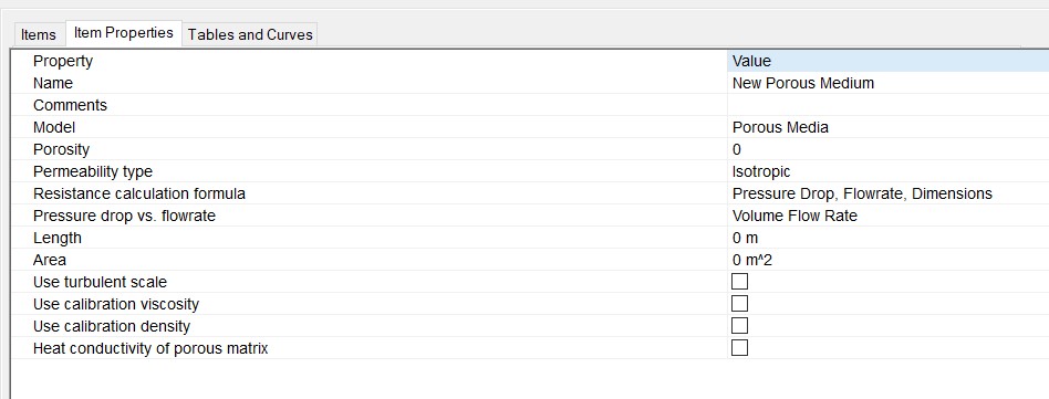
Porous Medium definition from SW Flow Simulation
Porosity:
The ratio of the volume of the interconnected pores to the total volume.

Permeability type:
Defines the permeability of the medium with respect to the flow direction. Four types of permeability are available in SOLIDWORKS Flow Simulation.
Resistance Calculation Formula:
It is used to calculate the flow resistance of the porous medium. The flow resistance coefficient is calculated by

Where P, ρ, V are Fluid Pressure, density, and velocity respectively.
User can specify the k vector components from one on the following equations.


The following formulae are used to specify the resistance of long narrow channel porous medium. This medium along with Unidirectional permeability type allows the user to simulate fluid flow through the arrays of tightly packed parallel thin tubes with high length – to- diameter ratio.


Volumetric Heat Exchange Co-efficient is calculated by

h: Heat Exchange Co-efficient between porous body’s inner surface and the fluid,

EXAMPLE:
Let’s see an example using the same concept in a Catalytic Converter to observe the flow patterns.
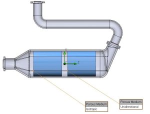

From the above image, we have defined two porous media in a catalytic converter. The first one (From right), a Unidirectional medium and the other, an Isotropic medium. The following image will show the flow pattern in each medium.
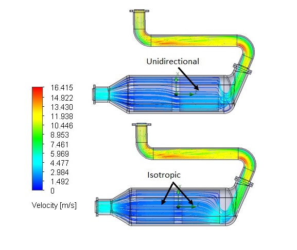
For the application of the catalytic converter, both the Unidirectional and Isotropic porous medium have their advantages.
We Urge You To Call Us For Any Doubts & Clarifications That You May Have. We Are Eager to Talk To You
Call Us: +91 7406663589
 (No Ratings Yet)
#365/8, Ground Floor, "Hasmitha Avenue", 16th Main, 4th T Block East, Jayanagar, 4th T Block East, Pattabhirama Nagar, Jayanagar, Bengaluru, Karnataka 560041
Rated 4.7/5 with a total of 62 reviews
"CARAX" Building 4th Floor, 105/1/1/4, Next to Radha Hotel, Pune-Mumbai Xpress Way,Baner,Pune 411045
Rated 4.7/5 with a total of 17 reviews
1002, LODHA Supremus, I-Think Techno Campus,Kanjurmarg EAST - MUMBAI, MH, India – 400042.
Rated 5/5 with a total of 51 reviews
508, Shiti Ratna Complex, Panchwati Cross Road, Ahmedabad-380006
Rated 4.1/5 with a total of 7 reviews
Kanda's Villa, II Floor, AE Block,3362 R, 8th Street, Anna Nagar, Chennai, Tamil Nadu 600040
Rated 4.6/5 with a total of 16 reviews
Flat no F1, first floor, Nakhate corner, Eknath rang mandir road,New Usmanpura, Aurangabad, 431005.
A-101, 1st Floor, The Hub Complex, opp. Shete Hospital, Mahatma Nagar, Parijat Nagar, Nashik, Maharashtra 422005.
Level 7, Octave 3B Salarpuria Sattva Knowledge City, Inorbit Mall Road, Raidurg Village, Hi-tech City, Hyderabad, Telangana - 500081, India

pin up yukle https://azerbaijancuisine.com/# pin up yukle
pin up az?rbaycan
п»їbest mexican online pharmacies mexican pharmacy mexican mail order pharmacies
medication from mexico pharmacy mexican northern doctors п»їbest mexican online pharmacies
medicine in mexico pharmacies pharmacies in mexico that ship to usa mexican drugstore online
buying prescription drugs in mexico online: mexican northern doctors – medication from mexico pharmacy
https://northern-doctors.org/# mexican drugstore online
mexico drug stores pharmacies mexican pharmaceuticals online buying from online mexican pharmacy
buying from online mexican pharmacy: northern doctors – buying prescription drugs in mexico
https://northern-doctors.org/# mexico pharmacies prescription drugs
https://northern-doctors.org/# mexican pharmaceuticals online
mexican pharmaceuticals online: mexican pharmacy online – mexico pharmacy
https://northern-doctors.org/# buying prescription drugs in mexico online
medication from mexico pharmacy medication from mexico pharmacy mexican mail order pharmacies
https://northern-doctors.org/# purple pharmacy mexico price list
mexico pharmacies prescription drugs: mexican drugstore online – medication from mexico pharmacy
https://northern-doctors.org/# mexican pharmaceuticals online
pharmacies in mexico that ship to usa: mexican pharmacy northern doctors – mexico pharmacies prescription drugs
https://northern-doctors.org/# buying prescription drugs in mexico online
mexican border pharmacies shipping to usa mexican northern doctors medication from mexico pharmacy
п»їbest mexican online pharmacies: northern doctors – medication from mexico pharmacy
https://northern-doctors.org/# medicine in mexico pharmacies
reputable mexican pharmacies online: mexican pharmacy online – medication from mexico pharmacy
mexican rx online: mexican pharmacy – buying prescription drugs in mexico
https://northern-doctors.org/# buying prescription drugs in mexico
best online pharmacies in mexico: mexican northern doctors – mexican pharmaceuticals online
buying prescription drugs in mexico online online mexican pharmacy mexico pharmacies prescription drugs
https://cmqpharma.com/# mexico pharmacies prescription drugs
best online pharmacies in mexico
mexico drug stores pharmacies online mexican pharmacy mexican border pharmacies shipping to usa
buying from online mexican pharmacy: online mexican pharmacy – mexico pharmacies prescription drugs
mexican pharmacy online mexican pharmacy mexican pharmaceuticals online
п»їbest mexican online pharmacies
http://cmqpharma.com/# purple pharmacy mexico price list
best online pharmacies in mexico
mexican mail order pharmacies mexican pharmacy mexican mail order pharmacies
reputable mexican pharmacies online cmqpharma.com reputable mexican pharmacies online
mexican mail order pharmacies cmq pharma mexican pharmacy
I like this website it’s a master piece! Glad I discovered this ohttps://69v.topn google.Blog monry
buy medicines online in india mail order pharmacy india mail order pharmacy india
https://indiapharmast.com/# india pharmacy mail order
onlinecanadianpharmacy 24 canadian drug canadian pharmacy ed medications
https://canadapharmast.com/# canadianpharmacyworld
purple pharmacy mexico price list purple pharmacy mexico price list mexican rx online
https://canadapharmast.com/# canadian world pharmacy
onlinecanadianpharmacy canadian pharmacy ltd canadian pharmacy drugs online
ciprofloxacin generic: ciprofloxacin over the counter – ciprofloxacin
amoxicillin tablet 500mg: amoxicillin 500 mg tablet price – cost of amoxicillin 30 capsules
how can i get cheap clomid without insurance: can i buy cheap clomid no prescription – where to buy generic clomid pill
cipro online no prescription in the usa: buy cipro cheap – cipro online no prescription in the usa
buy cipro online usa: ciprofloxacin order online – ciprofloxacin over the counter
doxycycline price australia: doxycycline tablets buy online – order doxycycline online australia
doxycycline 3142: doxycycline prescription online – doxycycline brand
doxycycline india price: purchase doxycycline online – doxycycline prescription cost
http://mexicandeliverypharma.com/# buying from online mexican pharmacy
mexican online pharmacies prescription drugs: best online pharmacies in mexico – п»їbest mexican online pharmacies
reputable mexican pharmacies online mexican pharmaceuticals online mexican border pharmacies shipping to usa
buying prescription drugs in mexico online: mexican pharmaceuticals online – mexican mail order pharmacies
medication from mexico pharmacy: medicine in mexico pharmacies – reputable mexican pharmacies online
mexican pharmaceuticals online: mexican pharmaceuticals online – mexican border pharmacies shipping to usa
mexican pharmaceuticals online buying prescription drugs in mexico mexican border pharmacies shipping to usa
http://mexicandeliverypharma.com/# mexican online pharmacies prescription drugs
medicine in mexico pharmacies: mexican mail order pharmacies – medicine in mexico pharmacies
pharmacies in mexico that ship to usa: п»їbest mexican online pharmacies – mexican border pharmacies shipping to usa
mexico pharmacies prescription drugs п»їbest mexican online pharmacies best online pharmacies in mexico
https://mexicandeliverypharma.com/# buying prescription drugs in mexico
pharmacies in mexico that ship to usa: purple pharmacy mexico price list – best online pharmacies in mexico
mexican mail order pharmacies: mexican border pharmacies shipping to usa – mexican pharmaceuticals online
mexico drug stores pharmacies: mexican drugstore online – mexico pharmacies prescription drugs
mexico pharmacy pharmacies in mexico that ship to usa mexican border pharmacies shipping to usa
mexican border pharmacies shipping to usa: buying from online mexican pharmacy – п»їbest mexican online pharmacies
purple pharmacy mexico price list: mexican mail order pharmacies – medication from mexico pharmacy
mexico drug stores pharmacies: buying from online mexican pharmacy – best online pharmacies in mexico
purple pharmacy mexico price list mexican pharmacy mexican drugstore online
https://mexicandeliverypharma.com/# mexican pharmaceuticals online
mexican mail order pharmacies: buying prescription drugs in mexico online – mexican online pharmacies prescription drugs
mexican online pharmacies prescription drugs: mexican online pharmacies prescription drugs – best online pharmacies in mexico
mexican border pharmacies shipping to usa: purple pharmacy mexico price list – purple pharmacy mexico price list
mexican rx online mexican rx online mexican border pharmacies shipping to usa
buying prescription drugs in mexico: mexican rx online – mexico drug stores pharmacies
п»їbest mexican online pharmacies: mexico drug stores pharmacies – mexican drugstore online
mexican online pharmacies prescription drugs: mexican mail order pharmacies – mexican mail order pharmacies
п»їbest mexican online pharmacies mexican mail order pharmacies mexican border pharmacies shipping to usa
Thank you for your sharing. I am worried that I lack creative ideas. It is your article that makes me full of hope. Thank you. But, I have a question, can you help me?
mexican mail order pharmacies: buying prescription drugs in mexico online – medicine in mexico pharmacies
mexican mail order pharmacies: п»їbest mexican online pharmacies – mexican drugstore online
mexican pharmaceuticals online: mexican pharmaceuticals online – mexican drugstore online
mexican mail order pharmacies reputable mexican pharmacies online mexico pharmacies prescription drugs
purple pharmacy mexico price list: purple pharmacy mexico price list – mexican drugstore online
mexican mail order pharmacies: buying prescription drugs in mexico – mexican online pharmacies prescription drugs
purple pharmacy mexico price list: mexican border pharmacies shipping to usa – buying prescription drugs in mexico online
mexican online pharmacies prescription drugs reputable mexican pharmacies online medicine in mexico pharmacies
mexican pharmaceuticals online: mexican border pharmacies shipping to usa – mexican mail order pharmacies
mexico drug stores pharmacies: buying from online mexican pharmacy – mexican online pharmacies prescription drugs
medicine in mexico pharmacies: buying prescription drugs in mexico online – reputable mexican pharmacies online
mexican pharmacy medicine in mexico pharmacies buying prescription drugs in mexico
mexico pharmacies prescription drugs: reputable mexican pharmacies online – mexican drugstore online
reputable mexican pharmacies online: mexican online pharmacies prescription drugs – mexican online pharmacies prescription drugs
mexican rx online: п»їbest mexican online pharmacies – п»їbest mexican online pharmacies
mexican pharmacy buying from online mexican pharmacy mexican online pharmacies prescription drugs
mexican pharmaceuticals online: buying prescription drugs in mexico – buying prescription drugs in mexico online
best online pharmacies in mexico: buying from online mexican pharmacy – mexican online pharmacies prescription drugs
mexican mail order pharmacies: medication from mexico pharmacy – buying from online mexican pharmacy
purple pharmacy mexico price list best online pharmacies in mexico reputable mexican pharmacies online
pharmacies in mexico that ship to usa: best online pharmacies in mexico – mexican mail order pharmacies
reputable mexican pharmacies online: mexico drug stores pharmacies – mexican online pharmacies prescription drugs
medicine in mexico pharmacies: mexico drug stores pharmacies – п»їbest mexican online pharmacies
mexico pharmacies prescription drugs buying from online mexican pharmacy mexican mail order pharmacies
mexican drugstore online: mexican rx online – best online pharmacies in mexico
purple pharmacy mexico price list: mexico drug stores pharmacies – mexican mail order pharmacies
mexican pharmacy medication from mexico pharmacy buying from online mexican pharmacy
mexican mail order pharmacies: medicine in mexico pharmacies – medicine in mexico pharmacies
п»їbest mexican online pharmacies: medication from mexico pharmacy – mexico pharmacies prescription drugs
medicine in mexico pharmacies: medication from mexico pharmacy – reputable mexican pharmacies online
mexican mail order pharmacies mexico drug stores pharmacies mexico drug stores pharmacies
mexican pharmaceuticals online: mexico drug stores pharmacies – reputable mexican pharmacies online
mexican drugstore online: mexican drugstore online – mexican pharmaceuticals online
buying prescription drugs in mexico online: mexican rx online – pharmacies in mexico that ship to usa
mexican border pharmacies shipping to usa mexican pharmacy mexican pharmacy
mexico drug stores pharmacies: mexican online pharmacies prescription drugs – medication from mexico pharmacy
medicine in mexico pharmacies: mexican pharmaceuticals online – reputable mexican pharmacies online
п»їbest mexican online pharmacies: buying from online mexican pharmacy – purple pharmacy mexico price list
medication from mexico pharmacy buying prescription drugs in mexico buying from online mexican pharmacy
buying prescription drugs in mexico: buying prescription drugs in mexico – mexican border pharmacies shipping to usa
buying prescription drugs in mexico: mexican border pharmacies shipping to usa – mexican drugstore online
mexico pharmacies prescription drugs mexican mail order pharmacies mexico pharmacy
mexican online pharmacies prescription drugs: buying from online mexican pharmacy – mexican pharmaceuticals online
medication from mexico pharmacy: medication from mexico pharmacy – п»їbest mexican online pharmacies
cost propecia without insurance cost cheap propecia online get generic propecia without dr prescription
generic prednisone otc: prednisone pack – buy prednisone online no script
https://zithromaxbestprice.pro/# zithromax capsules price
https://nolvadexbestprice.pro/# nolvadex online
get propecia no prescription buy generic propecia cheap propecia price
tamoxifen cyp2d6: tamoxifen 20 mg – alternatives to tamoxifen
https://zithromaxbestprice.pro/# zithromax capsules
https://cytotecbestprice.pro/# Cytotec 200mcg price
what happens when you stop taking tamoxifen buy nolvadex online common side effects of tamoxifen
tamoxifen for men: nolvadex steroids – does tamoxifen cause weight loss
http://prednisonebestprice.pro/# purchase prednisone canada
https://propeciabestprice.pro/# get generic propecia prices
nolvadex online tamoxifen lawsuit nolvadex only pct
average cost of prednisone: buy prednisone 5mg canada – prednisone in canada
generic tamoxifen: tamoxifen skin changes – tamoxifen generic
nolvadex online: buy tamoxifen – raloxifene vs tamoxifen
https://zithromaxbestprice.pro/# buy cheap generic zithromax
buy cytotec in usa: cytotec abortion pill – purchase cytotec
http://propeciabestprice.pro/# propecia sale
buy zithromax online with mastercard: buy zithromax online australia – can you buy zithromax over the counter in canada
propecia price: buy cheap propecia pill – buying propecia without prescription
cost generic propecia for sale: buy cheap propecia without a prescription – buying cheap propecia without rx
https://prednisonebestprice.pro/# prednisone 5 mg brand name
Farmacie online sicure: avanafil senza ricetta – acquisto farmaci con ricetta
farmacia online piГ№ conveniente: avanafil in farmacia – farmacie online affidabili
http://avanafil.pro/# farmacia online piГ№ conveniente
farmacia online: Cialis generico 20 mg 8 compresse prezzo – comprare farmaci online all’estero
п»їFarmacia online migliore: Cialis generico 5 mg prezzo – farmacie online sicure
п»їFarmacia online migliore: Cialis generico controindicazioni – farmaci senza ricetta elenco
farmacia online senza ricetta: avanafil in farmacia – comprare farmaci online all’estero
https://cialisgenerico.life/# farmacia online
acquistare farmaci senza ricetta: Avanafil prezzo – farmacia online
farmacia online senza ricetta: kamagra oral jelly – Farmacie on line spedizione gratuita
Farmacia online piГ№ conveniente: avanafil generico – Farmacia online piГ№ conveniente
http://kamagrait.pro/# migliori farmacie online 2024
acquistare farmaci senza ricetta: super kamagra – acquisto farmaci con ricetta
farmacie online affidabili: Cialis generico 20 mg 8 compresse prezzo – farmacie online sicure
cialis discount: cheapest tadalafil – cialis sales in victoria canada
http://tadalafil.auction/# cialis australia online shopping
cialis trial coupon: Generic Cialis without a doctor prescription – cialis with no prescription
https://tadalafil.auction/# overnight pharmacy 4u cialis
cialis soft tabs overnight: cialis without a doctor prescription – cialis with dapoxetine or viagra with dapoxetine better
viagra coupons: Viagra without a doctor prescription – viagra generic
http://sildenafil.llc/# viagra coupons
online erectile dysfunction: Best ED meds online – ed med online
http://mexicopharmacy.win/# mexican rx online
https://mexicopharmacy.win/# buying prescription drugs in mexico online
low cost ed medication
pharmacies in mexico that ship to usa: Best pharmacy in Mexico – п»їbest mexican online pharmacies
http://edpillpharmacy.store/# online ed treatments
cheap ed pills
https://indiapharmacy.shop/# indian pharmacy online
top online pharmacy india: Indian pharmacy international shipping – reputable indian pharmacies
http://edpillpharmacy.store/# discount ed meds
erectile dysfunction medication online
indian pharmacy online: Top online pharmacy in India – world pharmacy india
mexican border pharmacies shipping to usa: Certified Mexican pharmacy – mexico drug stores pharmacies
https://mexicopharmacy.win/# buying prescription drugs in mexico
ed meds on line: Best ED meds online – cheapest ed meds
https://indiapharmacy.shop/# cheapest online pharmacy india
online pharmacy india: Online pharmacy USA – online pharmacy india
http://mexicopharmacy.win/# mexico drug stores pharmacies
buy prescription drugs from india: Indian pharmacy international shipping – indianpharmacy com
https://mexicopharmacy.win/# mexico drug stores pharmacies
mexican online pharmacies prescription drugs: Best online Mexican pharmacy – medicine in mexico pharmacies
reputable indian pharmacies: indian pharmacy – best india pharmacy
http://mexicopharmacy.win/# mexican border pharmacies shipping to usa
where can i buy ed pills: Cheapest online ED treatment – ed prescriptions online
cheap ed pills: cheap ed pills online – ed medicines online
mexico drug stores pharmacies: Purple pharmacy online ordering – purple pharmacy mexico price list
Online medicine home delivery: Top online pharmacy in India – best online pharmacy india
mail order pharmacy india: indian pharmacy – п»їlegitimate online pharmacies india
world pharmacy india: best india pharmacy – top 10 online pharmacy in india
best online pharmacy india: Online medicine home delivery – reputable indian online pharmacy
buy cytotec online fast delivery: cytotec pills buy online – Cytotec 200mcg price
http://cytotec.pro/# buy cytotec online
cheap lipitor online: buy generic lipitor – cheapest generic lipitor
buy cytotec http://cytotec.pro/# buy cytotec over the counter
lasix 100mg
http://tamoxifen.bid/# tamoxifen for gynecomastia reviews
tamoxifen postmenopausal: buy tamoxifen online – tamoxifen joint pain
lisinopril 5mg lisinopril 2.5 cost compare zestril prices
Misoprostol 200 mg buy online https://lipitor.guru/# lipitor 40
lasix
lasix uses: lasix dosage – lasix 100 mg tablet
https://tamoxifen.bid/# does tamoxifen cause bone loss
cytotec buy online usa http://lisinopril.guru/# lisinopril cost uk
lasix dosage
lasix medication: furosemida – lasix pills
https://cytotec.pro/# cytotec abortion pill
order cytotec online https://furosemide.win/# furosemida 40 mg
lasix 40 mg
purchase cytotec purchase cytotec buy cytotec online fast delivery
lipitor tablets: cheapest ace inhibitor – lipitor 10mg price
lipitor 20 mg generic: cost of lipitor in canada – lipitor generic on line no prescription
https://furosemide.win/# lasix for sale
Misoprostol 200 mg buy online http://furosemide.win/# furosemide 100 mg
lasix 20 mg
buy misoprostol over the counter: cytotec best price – Abortion pills online
http://tamoxifen.bid/# common side effects of tamoxifen
buy cytotec: Misoprostol price in pharmacy – purchase cytotec
buy cytotec pills online cheap http://lisinopril.guru/# lisinopril 20 mg over the counter
lasix 100 mg
lisinopril medication prescription: buy lisinopril – lisinopril 20mg for sale
Cytotec 200mcg price http://lisinopril.guru/# lisinopril 5 mg price in india
lasix 100mg
benefits of tamoxifen: Purchase Nolvadex Online – tamoxifen endometriosis
furosemide 100mg: buy lasix online – lasix 40mg
order cytotec online http://lipitor.guru/# lipitor generic
furosemida
lasix medication: buy furosemide – lasix 40 mg
purchase cytotec https://cytotec.pro/# buy cytotec in usa
lasix 100 mg
prescription drug prices lisinopril: Lisinopril online prescription – lisinopril 20mg
lisinopril 10 mg prices: buy lisinopril – generic lisinopril 5 mg
pharmacies in mexico that ship to usa: buying prescription drugs in mexico online – mexico drug stores pharmacies
http://mexstarpharma.com/# mexican online pharmacies prescription drugs
http://mexstarpharma.com/# mexico drug stores pharmacies
canadian drugs online: global pharmacy canada – canadian pharmacy service
cheapest online pharmacy india best online pharmacy india india online pharmacy
http://mexstarpharma.com/# reputable mexican pharmacies online
https://mexstarpharma.online/# buying prescription drugs in mexico
best canadian online pharmacy canadian drugs online canada pharmacy
medication from mexico pharmacy: purple pharmacy mexico price list – buying from online mexican pharmacy
mexico drug stores pharmacies: best online pharmacies in mexico – п»їbest mexican online pharmacies
http://mexstarpharma.com/# mexico drug stores pharmacies
https://mexstarpharma.com/# pharmacies in mexico that ship to usa
buy prescription drugs from india: buy medicines online in india – online shopping pharmacy india
http://easyrxindia.com/# online pharmacy india
top online pharmacy india: indian pharmacy paypal – world pharmacy india
indianpharmacy com: п»їlegitimate online pharmacies india – indian pharmacy online
https://mexstarpharma.com/# mexico drug stores pharmacies
deneme bonusu: deneme bonusu veren siteler – bonus veren siteler
https://sweetbonanza.network/# sweet bonanza guncel
slot bahis siteleri: yasal slot siteleri – yeni slot siteleri
deneme bonusu veren siteler: deneme bonusu veren siteler – bahis siteleri
deneme veren slot siteleri: bonus veren slot siteleri – guvenilir slot siteleri
http://sweetbonanza.network/# sweet bonanza demo turkce
en guvenilir slot siteleri: yasal slot siteleri – en guvenilir slot siteleri
https://slotsiteleri.bid/# slot kumar siteleri
guvenilir slot siteleri: slot oyun siteleri – deneme veren slot siteleri
https://slotsiteleri.bid/# en iyi slot siteleri
en iyi slot siteler: deneme bonusu veren slot siteleri – deneme veren slot siteleri
My friend and I have been discussing personal blogs and online journaling. She feels that personal feelings and such should not expressed in such open forums. I see no problem with it. Share your thoughts:. 1. Do you blog or journal?. 2. Do you prefer face to face expression of feelings over written communication?.
This blog is definitely rather handy since I’m at the moment creating an internet floral website – although I am only starting out therefore it’s really fairly small, nothing like this site. Can link to a few of the posts here as they are quite. Thanks much. Zoey Olsen
https://sweetbonanza.network/# sweet bonanza siteleri
canl? slot siteleri: en yeni slot siteleri – slot bahis siteleri
https://vavada.auction/# vavada
1вин официальный сайт: 1win – 1вин зеркало
pin up casino пин ап казино вход pin up
пин ап казино: пин ап вход – pin up casino
https://pin-up.diy/# пин ап вход
пин ап вход: пин ап вход – пин ап зеркало
1xbet официальный сайт: 1xbet зеркало – 1хбет зеркало
https://1win.directory/# 1вин зеркало
http://pin-up.diy/# пин ап казино вход
1win: 1вин зеркало – 1win официальный сайт
https://pin-up.diy/# пин ап казино
express pharmacy online: texas state board of pharmacy – purdue pharmacy store
https://pharm24on.com/# pharmacy mistake methotrexate
Azulfidine
rx express pharmacy: tadacip online pharmacy – adderall online pharmacy
online pharmacy ambien no prescription: sam’s club pharmacy hours – bupropion sr pharmacy
https://onlineph24.com/# real rx pharmacy
Olanzapine
best online pharmacy ativan: klonopin indian pharmacy – Florinef
guardian pharmacy loratadine: mail order pharmacy – domperidone mexican pharmacy
https://onlineph24.com/# tacrolimus online pharmacy
target pharmacy lipitor generic
united pharmacy propecia: Trecator SC – boots pharmacy viagra
pharmacy store online: tesco pharmacy viagra cost – caverta online pharmacy
lidocaine patch online pharmacy: zyprexa pharmacy – review online pharmacy
pain meds online without doctor prescription: roman online pharmacy – drug store pharmacy
kamagra 365 pharmacy: online pharmacies – vyvanse online pharmacy
online shopping pharmacy india Online medicine order top 10 pharmacies in india
mexico drug stores pharmacies: medication from mexico pharmacy – buying prescription drugs in mexico
http://mexicopharmacy.cheap/# mexico pharmacies prescription drugs
indianpharmacy com: reputable indian online pharmacy – best india pharmacy
indian pharmacy: world pharmacy india – top 10 pharmacies in india
https://indianpharmacy.company/# online shopping pharmacy india
india pharmacy mail order pharmacy website india indian pharmacies safe
reputable indian online pharmacy: rx pharmacy online – pharmacy metronidazole and alcohol
how much is percocet at the pharmacy mexican pharmacy percocet percocet cost pharmacy
https://mexicopharmacy.cheap/# mexican mail order pharmacies
rhinocort online pharmacy: rx discount pharmacy dade city fl – doctor prescription
clomiphene citrate online pharmacy rite aid pharmacy store number erectile dysfunction causes
mexico drug stores pharmacies: mexican border pharmacies shipping to usa – п»їbest mexican online pharmacies
https://indianpharmacy.company/# reputable indian online pharmacy
medicine in mexico pharmacies mexican rx online mexican pharmaceuticals online
pharmacy website india: world pharmacy india – Online medicine order
india pharmacy mail order indianpharmacy com india online pharmacy
mexican border pharmacies shipping to usa: mexico drug stores pharmacies – medicine in mexico pharmacies
indian pharmacy online: world pharmacy india – indian pharmacy paypal
mexico drug stores pharmacies medicine in mexico pharmacies mexico drug stores pharmacies
pharmacies in mexico that ship to usa: medicine in mexico pharmacies – п»їbest mexican online pharmacies
Keep up the good piece of work, I read few posts on this website and I think that your web blog is very interesting and holds bands of wonderful information.
https://pharmbig24.online/# medco pharmacy lipitor
clarinex pharmacy coupon Sporanox rx express pharmacy hurley ms
best online pharmacies in mexico: pharmacies in mexico that ship to usa – buying prescription drugs in mexico online
mexican mail order pharmacies medication from mexico pharmacy п»їbest mexican online pharmacies
https://pharmbig24.online/# mexico pharmacy adipex
wal mart store pharmacy: central rx pharmacy – accurate rx pharmacy columbia mo
buy medicines online in india indian pharmacy online cheapest online pharmacy india
I real glad to find this internet site on bing, just what I was searching for : D likewise saved to bookmarks.
buying prescription drugs in mexico online: mexican rx online – mexico pharmacies prescription drugs
Super P-Force: benzodiazepines online pharmacy – generic viagra mexico pharmacy
https://pharmbig24.com/# online pharmacy paypal
online pharmacy reviews adipex pro cialis pharmacy hydroxyzine online pharmacy
top 10 online pharmacy in india: best india pharmacy – top online pharmacy india
indian pharmacies safe: best india pharmacy – reputable indian online pharmacy
http://mexicopharmacy.cheap/# mexico drug stores pharmacies
buying prescription drugs in mexico online mexico drug stores pharmacies mexico drug stores pharmacies
buy medicines online in india: india pharmacy – top 10 pharmacies in india
buy prescription drugs from india indian pharmacy world pharmacy india
the pharmacy: online pharmacy legal – online mexican pharmacy
gates of olympus demo turkce gates of olympus giris gates of olympus demo oyna
betine promosyon kodu 2024 betine guncel betine giris
http://starzbet.shop/# starzbet guncel giris
gates of olympus demo gates of olympus demo turkce Gates of Olympus
http://starzbet.shop/# starzbet guncel giris
https://betine.online/# betine giris
casibom guncel giris casibom giris casibom 158 giris
http://casibom.auction/# casibom guncel giris
Gates of Olympus gates of olympus oyna demo Gates of Olympus
http://sildenafilo.men/# comprar viagra en espaГ±a amazon
comprar sildenafilo cinfa 100 mg espaГ±a: viagra para hombre precio farmacias – viagra online cerca de zaragoza
https://tadalafilo.bid/# farmacia barata
farmacia online barcelona
sildenafilo 100mg precio farmacia comprar viagra viagra para hombre precio farmacias
farmacia online madrid: comprar cialis original – farmacia online espaГ±a envГo internacional
farmacia online espaГ±a envГo internacional: Cialis sin receta – farmacia online envГo gratis
http://tadalafilo.bid/# farmacia en casa online descuento
http://farmaciaeu.com/# farmacia en casa online descuento
farmacias online seguras en espaГ±a
farmacia online madrid farmacia online envio gratis murcia farmacias online seguras en espaГ±a
http://sildenafilo.men/# п»їViagra online cerca de Madrid
farmacia online madrid: precio cialis en farmacia con receta – farmacias online baratas
farmacias online seguras en espaГ±a: farmacia 24 horas – farmacia online madrid
http://sildenafilo.men/# comprar viagra en espaГ±a
comprar viagra en espaГ±a: Viagra sildenafilo – viagra entrega inmediata
http://sildenafilo.men/# viagra online cerca de bilbao
farmacias online seguras en espaГ±a
farmacias online seguras: precio cialis en farmacia con receta – farmacia online barcelona
http://farmaciaeu.com/# farmacias online seguras en espaГ±a
viagra online cerca de malaga: sildenafilo – sildenafilo cinfa sin receta
https://tadalafilo.bid/# farmacia online 24 horas
farmacia online envГo gratis
viagra para hombre precio farmacias similares: sildenafilo precio – comprar viagra en espaГ±a envio urgente
https://farmaciaeu.com/# farmacia online barata
farmaci senza ricetta elenco: Cialis generico farmacia – farmacia online senza ricetta
farmacie online sicure: Cialis generico farmacia – farmacie online autorizzate elenco
migliori farmacie online 2024 Farmacia online miglior prezzo Farmacia online piГ№ conveniente
Farmacie on line spedizione gratuita Cialis generico recensioni farmacie online sicure
https://farmaciait.men/# acquistare farmaci senza ricetta
Farmacie on line spedizione gratuita
farmacie online sicure: Farmacia online migliore – acquistare farmaci senza ricetta
cialis farmacia senza ricetta: viagra originale in 24 ore contrassegno – viagra cosa serve
acquistare farmaci senza ricetta Farmacia online migliore farmacia online piГ№ conveniente
farmaci senza ricetta elenco Farmacie on line spedizione gratuita farmaci senza ricetta elenco
Farmacie online sicure: Cialis generico 20 mg 8 compresse prezzo – acquisto farmaci con ricetta
top farmacia online: Farmacie on line spedizione gratuita – farmacia online piГ№ conveniente
http://farmaciait.men/# Farmacie online sicure
п»їFarmacia online migliore
alternativa al viagra senza ricetta in farmacia: viagra online siti sicuri – cerco viagra a buon prezzo
farmacia online piГ№ conveniente Farmacia online piu conveniente Farmacie on line spedizione gratuita
alternativa al viagra senza ricetta in farmacia viagra generico kamagra senza ricetta in farmacia
esiste il viagra generico in farmacia: viagra prezzo – pillole per erezione immediata
gel per erezione in farmacia: viagra prezzo farmacia 2023 – kamagra senza ricetta in farmacia
cialis farmacia senza ricetta viagra naturale in farmacia senza ricetta alternativa al viagra senza ricetta in farmacia
http://tadalafilit.com/# farmacia online senza ricetta
Farmacie on line spedizione gratuita
viagra naturale in farmacia senza ricetta viagra senza prescrizione viagra generico sandoz
top farmacia online: Cialis generico 20 mg 8 compresse prezzo – farmacie online autorizzate elenco
comprare farmaci online con ricetta Cialis generico prezzo farmacie online autorizzate elenco
farmaci senza ricetta elenco farmacia online migliore Farmacie on line spedizione gratuita
http://sildenafilit.pro/# le migliori pillole per l’erezione
comprare farmaci online all’estero
п»їFarmacia online migliore: BRUFEN 600 acquisto online – Farmacie on line spedizione gratuita
comprare farmaci online con ricetta: Farmacia online migliore – comprare farmaci online all’estero
comprare farmaci online all’estero Cialis generico farmacia Farmacie online sicure
alternativa al viagra senza ricetta in farmacia viagra farmacia kamagra senza ricetta in farmacia
Farmacia online piГ№ conveniente: BRUFEN 600 acquisto online – farmacia online
comprare farmaci online con ricetta: Ibuprofene 600 generico prezzo – acquisto farmaci con ricetta
п»їFarmacia online migliore Brufen 600 prezzo top farmacia online
viagra acquisto in contrassegno in italia pillole per erezione immediata viagra acquisto in contrassegno in italia
farmacie online affidabili: Farmacie on line spedizione gratuita – Farmacie online sicure
http://tadalafilit.com/# farmacia online
comprare farmaci online all’estero
comprare farmaci online con ricetta Cialis generico recensioni farmacia online senza ricetta
Farmacie online sicure Cialis generico farmacia Farmacie online sicure
farmacia online senza ricetta: Cialis generico 5 mg prezzo – farmacia online senza ricetta
https://ventolininhaler.pro/# generic ventolin price
buy neurontin uk cost of neurontin 800 mg cost of neurontin 100mg
buy prednisone 5mg canada: prednisone 1 mg tablet – prednisone 5 mg tablet rx
lasix 100 mg: furosemide online – lasix 100mg
furosemida 40 mg: furosemide online – lasix for sale
rybelsus rybelsus price rybelsus
http://furosemide.men/# buy furosemide online
cheap ventolin online: Buy Ventolin inhaler online – ventolin 108 mcg
cost of ventolin in usa: ventolin otc usa – ventolin 95mcg
lasix generic: cheap lasix – buy lasix online
ventolin spray: Ventolin inhaler – can i buy ventolin over the counter in usa
ventolin 50 mg: Ventolin inhaler – buy ventolin online europe
buy cheap neurontin: neurontin 100mg tablets – neurontin 2018
http://furosemide.men/# lasix generic name
lasix medication: cheap lasix – lasix tablet
neurontin prescription coupon: neurontin – neurontin 30 mg
neurontin sale: neurontin capsules 100mg – neurontin capsule 400 mg
indian pharmacy: Indian pharmacy international shipping – online shopping pharmacy india
п»їbest mexican online pharmacies mexican pharma buying prescription drugs in mexico online
india pharmacy mail order: online Indian pharmacy – top 10 online pharmacy in india
https://canadapharma.shop/# canadian pharmacy
mexico pharmacies prescription drugs: buying prescription drugs in mexico – purple pharmacy mexico price list
http://indiadrugs.pro/# indian pharmacy online
buying prescription drugs in mexico medication from mexico mexican pharmaceuticals online
cheapest online pharmacy india: online Indian pharmacy – best online pharmacy india
https://canadapharma.shop/# canadian pharmacy world reviews
buy prescription drugs from india: Indian pharmacy online – world pharmacy india
canadapharmacyonline com Online medication home delivery canadian pharmacy meds
http://indiadrugs.pro/# top online pharmacy india
http://canadapharma.shop/# certified canadian international pharmacy
pharmacies in mexico that ship to usa buying prescription drugs in mexico online п»їbest mexican online pharmacies
http://mexicanpharma.icu/# reputable mexican pharmacies online
I like this web site so much, bookmarked.
canadian pharmacy king reviews best canadian pharmacy to buy from northwest pharmacy canada
mexico pharmacies prescription drugs: medication from mexico – mexican mail order pharmacies
buying from online mexican pharmacy
best india pharmacy: indian pharmacy – indianpharmacy com
http://indiadrugs.pro/# best online pharmacy india
Achat mГ©dicament en ligne fiable: Cialis generique achat en ligne – pharmacie en ligne
http://pharmaciepascher.pro/# pharmacie en ligne france fiable
pharmacie en ligne france livraison internationale Pharmacies en ligne certifiees pharmacie en ligne sans ordonnance
п»їViagra sans ordonnance 24h: Viagra sans ordonnance 24h – Acheter viagra en ligne livraison 24h
pharmacie en ligne sans ordonnance: Pharmacie en ligne livraison Europe – Pharmacie sans ordonnance
Quand une femme prend du Viagra homme viagra en ligne Viagra vente libre allemagne
http://clssansordonnance.icu/# trouver un mГ©dicament en pharmacie
acheter mГ©dicament en ligne sans ordonnance: Medicaments en ligne livres en 24h – pharmacie en ligne france livraison belgique
Achat mГ©dicament en ligne fiable: pharmacie en ligne sans ordonnance – pharmacie en ligne
trouver un mГ©dicament en pharmacie Cialis sans ordonnance pas cher pharmacie en ligne fiable
Pharmacie en ligne livraison Europe: pharmacie en ligne fiable – pharmacie en ligne sans ordonnance
Some really nice and useful info on this web site, likewise I think the style contains wonderful features.
http://vgrsansordonnance.com/# Viagra homme prix en pharmacie sans ordonnance
п»їpharmacie en ligne france: Acheter Cialis 20 mg pas cher – pharmacie en ligne france fiable
Acheter viagra en ligne livraison 24h Meilleur Viagra sans ordonnance 24h Viagra pas cher paris
Hey there! I just wanted to ask if you ever have any trouble with hackers? My last blog (wordpress) was hacked and I ended up losing several weeks of hard work due to no backup. Do you have any methods to stop hackers?
ozempic generic buy cheap ozempic buy ozempic
Ozempic without insurance: ozempic – ozempic generic
https://ozempic.art/# ozempic
semaglutide tablets: rybelsus pill – rybelsus pill
semaglutide online rybelsus cost semaglutide online
buy ozempic pills online: ozempic cost – buy cheap ozempic
https://ozempic.art/# ozempic coupon
https://ozempic.art/# ozempic cost
ozempic: Ozempic without insurance – ozempic cost
buy ozempic pills online ozempic coupon ozempic cost
ozempic cost: ozempic – ozempic cost
https://rybelsus.shop/# rybelsus coupon
Ozempic without insurance: buy ozempic – buy cheap ozempic
ozempic generic ozempic cost ozempic cost
Ozempic without insurance: buy cheap ozempic – ozempic cost
semaglutide tablets: buy rybelsus online – buy semaglutide pills
http://ozempic.art/# buy ozempic pills online
rybelsus coupon rybelsus price rybelsus coupon
http://ozempic.art/# Ozempic without insurance
buy semaglutide online: rybelsus cost – rybelsus pill
https://ozempic.art/# buy ozempic
semaglutide tablets: rybelsus price – semaglutide online
ozempic online ozempic ozempic online
buy ozempic pills online: buy ozempic – ozempic cost
http://ozempic.art/# ozempic generic
ozempic buy cheap ozempic ozempic
ozempic: Ozempic without insurance – ozempic generic
https://rybelsus.shop/# rybelsus price
rybelsus pill: semaglutide online – rybelsus price
buy semaglutide online cheapest rybelsus pills buy semaglutide pills
buy semaglutide online: rybelsus price – rybelsus pill
http://rybelsus.shop/# semaglutide online
https://rybelsus.shop/# buy semaglutide online
cheapest rybelsus pills cheapest rybelsus pills cheapest rybelsus pills
http://rybelsus.shop/# semaglutide online
buy ozempic pills online: ozempic cost – buy ozempic pills online
cheapest rybelsus pills rybelsus coupon semaglutide online
https://rybelsus.shop/# semaglutide cost
buy ozempic pills online ozempic coupon buy cheap ozempic
http://ozempic.art/# buy ozempic
pin up casino pin up aviator pin up casino giris
pin up aviator: pin-up casino giris – pin up casino
пинап кз пинап кз пин ап казино
пинап казино: пин ап казино вход – пин ап казино
пин ап кз http://pinupturkey.pro/# pin up giris
пин ап казино онлайн
pin up bet: pin-up casino giris – pin-up casino
pin up casino guncel giris pin-up casino giris pin up guncel giris
пин ап http://pinupru.site/# пин ап казино зеркало
пинап казино
pin up: пин ап казахстан – пин ап 634
пин ап официальный сайт: пин ап – пин ап
pin up aviator pin up pin up casino giris
пин ап казахстан: пин ап казахстан – пин ап казино
пин ап кз: пин ап кз – пинап кз
https://pinupturkey.pro/# pin up casino guncel giris
pin up https://pinupaz.bid/# pin up az
пин ап казино вход
pin up зеркало: pin up зеркало – pin up
pin up casino pin up aviator pin up casino guncel giris
pin up казино http://pinupaz.bid/# pin-up casino giris
пин ап кз
pin up 306: pin-up oyunu – pin up
пин ап кз пин ап казахстан пин ап кз
пин ап кз https://pinupturkey.pro/# pin up casino
пинап кз
pin up guncel giris pin up casino guncel giris pin up aviator
pin up https://pinupru.site/# пин ап вход
пин ап казино вход
https://stromectol.agency/# minocycline 50 mg online
https://stromectol.agency/# where can i buy oral ivermectin
buy zithromax online cheap
https://zithromax.company/# buy zithromax
https://stromectol.agency/# minocycline 100mg otc
zithromax 500 zithromax best price zithromax online australia
zithromax 1000 mg online: generic zithromax – zithromax cost canada
https://amoxil.llc/# where can i get amoxicillin
https://gabapentin.auction/# how much is generic neurontin
zithromax for sale us
amoxicillin canada price amoxicillin cheapest price buying amoxicillin in mexico
minocycline hcl: stromectol best price – buy ivermectin for humans australia
https://stromectol.agency/# minocycline 100mg tablets for human
http://stromectol.agency/# stromectol xr
https://stromectol.agency/# stromectol without prescription
can you buy zithromax over the counter in canada
Rybelsus 14 mg price Rybelsus 14 mg price rybelsus generic
gabapentin generic: order gabapentin – buy gabapentin
https://stromectol.agency/# ivermectin 0.5% brand name
https://gabapentin.auction/# neurontin 4 mg
https://stromectol.agency/# dynacin minocycline
minocycline 50mg stromectol for sale minocin 50 mg for scabies
https://semaglutide.win/# buy rybelsus
buy cheap generic zithromax
buy zithromax 500mg online: zithromax azithromycin – how to get zithromax over the counter
https://semaglutide.win/# Semaglutide pharmacy price
amoxicillin without prescription buy amoxil amoxicillin for sale online
https://zithromax.company/# cost of generic zithromax
zithromax 500mg price
https://semaglutide.win/# Buy compounded semaglutide online
stromectol 3mg: what does minocycline treat – stromectol 3 mg tablets price
https://amoxil.llc/# amoxicillin 500 mg capsule
Rybelsus 7mg buy rybelsus rybelsus price
https://stromectol.agency/# buy minocycline
zithromax capsules
https://stromectol.agency/# stromectol brand
neurontin price australia: neurontin 600 mg tablet – neurontin 214
Great post. I was checking continuously this weblog and I am inspired! Very helpful info specifically the final section 🙂 I deal with such information much. I used to be seeking this particular information for a very lengthy time. Thanks and good luck.
http://gabapentin.auction/# neurontin online
generic zithromax azithromycin order zithromax can you buy zithromax online
http://gabapentin.auction/# neurontin capsule 600mg
buy cheap generic zithromax
http://semaglutide.win/# cheap Rybelsus 14 mg
zithromax 500 mg: zithromax capsules 250mg – can you buy zithromax over the counter in australia
https://zithromax.company/# zithromax 500 mg for sale
semaglutide Rybelsus 7mg rybelsus
https://amoxil.llc/# amoxicillin 500mg over the counter
https://gabapentin.auction/# neurontin 200 mg price
zithromax for sale online
neurontin 600 mg price: buy gabapentin – buy neurontin 100 mg canada
http://stromectol.agency/# minocycline hcl
rybelsus buy rybelsus rybelsus cost
https://gabapentin.auction/# buy brand neurontin
zithromax drug
amoxicillin online canada: buy amoxil – amoxil generic
where can i buy zithromax uk order zithromax zithromax 250 mg
https://amoxil.llc/# amoxicillin in india
zithromax price canada
https://amoxil.llc/# amoxicillin 500 mg cost
rybelsus: Rybelsus 14 mg price – rybelsus
zithromax tablets order zithromax how to get zithromax online
http://semaglutide.win/# Semaglutide pharmacy price
https://amoxil.llc/# where can i buy amoxocillin
generic zithromax medicine
where to get zithromax over the counter: zithromax best price – buy zithromax online australia
https://zithromax.company/# generic zithromax medicine
Rybelsus 7mg rybelsus generic rybelsus price
http://stromectol.agency/# stromectol over the counter
zithromax 250
online shopping pharmacy india: indian pharmacy paypal – india pharmacy mail order
buy prescription drugs from india pharmacy website india india online pharmacy
http://indianpharmdelivery.com/# buy medicines online in india
online pharmacy india
erection pills viagra online http://indianpharmdelivery.com/# mail order pharmacy india
mexican rx online: п»їbest mexican online pharmacies – mexican drugstore online
top 10 online pharmacy in india: indian pharmacy paypal – buy medicines online in india
reputable indian pharmacies п»їlegitimate online pharmacies india buy prescription drugs from india
best ed pills at gnc http://drugs24.pro/# ed treatment drugs
online drugstore: ed pills – canadian drugstore online
https://mexicanpharm24.pro/# mexican rx online
indianpharmacy com
cheapest online pharmacy india: cheapest online pharmacy india – reputable indian pharmacies
ed pills online pharmacy muse ed drug cheap ed pills
ed meds online pharmacy: ed drugs online – male dysfunction
best pharmacy online http://mexicanpharm24.pro/# mexico pharmacies prescription drugs
drugs online: herbal ed treatment – ed clinic
natural herbs for ed online ed medications ed men
https://drugs24.pro/# the best ed pills
india online pharmacy
purple pharmacy mexico price list: mexican mail order pharmacies – medicine in mexico pharmacies
ed and diabetes cheap medications buy drug online
world pharmacy india: mail order pharmacy india – indian pharmacy online
http://indianpharmdelivery.com/# top online pharmacy india
india online pharmacy
doctors for erectile dysfunction https://indianpharmdelivery.com/# world pharmacy india
viagra without doctor prescription amazon: homepage – best male enhancement pills
best india pharmacy top online pharmacy india Online medicine home delivery
п»їbest mexican online pharmacies: purple pharmacy mexico price list – medicine in mexico pharmacies
best ed pills https://mexicanpharm24.pro/# mexico pharmacies prescription drugs
http://mexicanpharm24.pro/# mexico pharmacies prescription drugs
п»їlegitimate online pharmacies india
indianpharmacy com india pharmacy mail order cheapest online pharmacy india
ed clinic http://indianpharmdelivery.com/# top online pharmacy india
buying prescription drugs in mexico online mexico drug stores pharmacies medicine in mexico pharmacies
http://mexicanpharm24.pro/# purple pharmacy mexico price list
buy medicines online in india
http://stromectol1st.shop/# stromectol cream
best india pharmacy
buy minocycline 50 mg otc buy online buy minocycline 50 mg online
minocycline for acne 100mg: stromectol 1st – minocycline 100 mg
rybelsus generic: cheaper – semaglutide
Paxlovid buy online: check this – paxlovid for sale
buy Clopidogrel over the counter: plavix price – cheap plavix antiplatelet drug
http://stromectol1st.shop/# topical ivermectin cost
Online medicine home delivery
rybelsus Semaglutide pharmacy price buy rybelsus
buy Clopidogrel over the counter: clopidogrel pills – Cost of Plavix without insurance
price of stromectol: stromectol fast delivery – ivermectin 1%cream
https://clopidogrel.pro/# generic plavix
ed dysfunction treatment
stromectol tab price stromectol 1st stromectol price
https://stromectol1st.shop/# minocycline 100 mg without prescription
reputable indian online pharmacy
rybelsus.icu: order Rybelsus – good price
п»їpaxlovid: paxlovid shop – paxlovid pill
semaglutide good price good price
http://rybelsus.icu/# Buy semaglutide
online ed medications
http://stromectol1st.shop/# ivermectin pills canada
india pharmacy
Clopidogrel 75 MG price: plavix price – buy clopidogrel online
buy rybelsus: buy rybelsus – Buy semaglutide
minocycline coupon stromectol fast delivery stromectol in canada
Cost of Plavix without insurance: clopidogrel pro – plavix best price
paxlovid price: paxlovid cost without insurance – paxlovid india
https://paxlovid1st.shop/# paxlovid covid
real viagra without a doctor prescription usa
https://stromectol1st.shop/# order minocycline 50 mg
online pharmacy india
ivermectin topical stromectol shop stromectol tablets for humans for sale
paxlovid generic: paxlovid 1st – paxlovid generic
stromectol 3 mg tablet: stromectol shop – price of ivermectin liquid
https://paxlovid1st.shop/# paxlovid pharmacy
male ed
buy plavix generic pills п»їplavix generic
http://stromectol1st.shop/# stromectol ivermectin buy
indian pharmacy online
semaglutide: rybelsus cost – rybelsus cost
buy rybelsus: rybelsus cost – good price
cheap plavix antiplatelet drug here Cost of Plavix on Medicare
paxlovid buy: shop – paxlovid pharmacy
http://stromectol1st.shop/# buy ivermectin
online shopping pharmacy india
minocycline generic name: stromectol fast delivery – ivermectin cream cost
cheap plavix antiplatelet drug generic pills Clopidogrel 75 MG price
cost of ivermectin cream: stromectol shop – cost of ivermectin lotion
paxlovid buy: paxlovid cost without insurance – buy paxlovid online
paxlovid price paxlovid price buy paxlovid online
https://stromectol1st.shop/# ivermectin 3 mg dose
buy medicines online in india
rybelsus generic: Semaglutide pharmacy price – buy semaglutide online
https://1winbrasil.win/# pin-up
пинап казино
pin-up: pinup az – pin-up
casino sitesi: canl? casino – canl? casino siteleri
пин ап зеркало пин ап пин ап
https://1wintr.fun/# canl? casino
пин ап казино вход
1хставка: 1хставка – 1xbet официальный сайт
pin-up: pin up 306 – pin-up casino giris
pin-up casino giris: pin-up – pin up azerbaycan
пин ап кз: пинап кз – пин ап
пин ап пин ап официальный сайт пин ап официальный сайт
pin up casino: pin up azerbaycan – pin up 306
canl? casino siteleri: casino oyunlar? – casino siteleri
пин ап: пин ап – пин ап
casino oyunlar?: slot casino siteleri – en iyi casino siteleri
https://1wintr.fun/# h?zl? casino
пинап казино
pin up kz: пин ап – пинап кз
1хставка: 1xbet – 1хставка
pin up casino pin up 306 pin up
пинап: пинап – pin up kz
http://1winci.icu/# пин ап вход
пин ап казино вход
pin up: pin-up casino giris – pin up 306
cazino: casino sitesi – casino oyunlar?
1xbet зеркало: 1xbet зеркало – 1xbet официальный сайт
https://1wintr.fun/# casino oyunlar?
пинап
pin up 306 pin-up casino giris pin up
пин ап: пинап зеркало – пинап зеркало
h?zl? casino: casino oyunlar? – slot casino siteleri
en iyi casino siteleri: cazino – canl? casino siteleri
пин ап: пинап зеркало – пин ап зеркало
pin up pin up kz пинап
пин ап официальный сайт: пин ап официальный сайт – пин ап официальный сайт
1xbet скачать: 1xbet скачать – 1хбет
http://1winindia.tech/# pin up
пин ап казино
pin-up casino giris: pin-up – pin-up
1xbet зеркало: 1xbet официальный сайт – 1хбет
https://1winbrasil.win/# pin-up
пинап
casino sitesi: canl? casino siteleri – cazino
https://indianpharm1st.com/# indianpharmacy com
buy ed drugs online how can i order prescription drugs without a doctor vitamins for ed
buying prescription drugs in mexico online: mexican online pharmacies prescription drugs – mexican online pharmacies prescription drugs
ed medications list: cheap medication online – medication online
https://drugs1st.store/# buy prescription drugs without doctor
indian pharmacy online: online pharmacy india – top online pharmacy india
buying prescription drugs in mexico purple pharmacy mexico price list mexico pharmacies prescription drugs
mexican pharmaceuticals online: mexican online pharmacies prescription drugs – mexican mail order pharmacies
best online pharmacy india: india online pharmacy – best india pharmacy
http://mexicanpharm1st.com/# mexican drugstore online
best online pharmacies in mexico: mexican mail order pharmacies – mexico drug stores pharmacies
top 10 online pharmacy in india: п»їlegitimate online pharmacies india – best online pharmacy india
https://drugs1st.store/# ed drugs
causes for ed: buy prescription drugs online legally – ed treatment review
buying prescription drugs in mexico online п»їbest mexican online pharmacies medication from mexico pharmacy
buying prescription drugs in mexico: mexican rx online – mexican online pharmacies prescription drugs
purple pharmacy mexico price list: medication from mexico pharmacy – mexican drugstore online
http://indianpharm1st.com/# buy prescription drugs from india
reputable mexican pharmacies online: mexican rx online – pharmacies in mexico that ship to usa
mexican online pharmacies prescription drugs mexican mail order pharmacies buying prescription drugs in mexico online
https://mexicanpharm1st.com/# mexican border pharmacies shipping to usa
buy medicines online in india: indianpharmacy com – best india pharmacy
medication for ed: drug prices comparison – buy prescription drugs without doctor
http://pinupzerkalo.fun/# пинко
pin-up pin up casino pin up casino
pin-up casino giris: pin up 306 – pin-up
https://pinupzerkalo.fun/# бонусы пин ап
pin up casino
https://pinup-az.bid/# pin up azerbaycan
пин ап 634 пинап казино пин ап казино
pinup az: pin up casino – pinup
http://pinupzerkalo.fun/# пин ап зеркало
pin up casino
https://pinup-az.bid/# pin up casino
sweet bonanza tr: sweetbonanzatr.pro – sweet bonanza
https://sweetbonanzatr.pro/# sweet bonanza oyna
pinup bet and casino
pin up azerbaycan pin up pinup
sweet bonanza oyna: sweet bonanza – sweet bonanza
пин ап 634: пин ап казино онлайн – пин ап 634
пин ап казино: Пин Ап Казино Официальный Сайт в России – пин ап зеркало
http://pinup-az.bid/# pin-up casino giris
http://pinup-az.bid/# pin up casino
pin up win
https://pinupzerkalo.fun/# Официальный Сайт
pin up casino
http://sweetbonanzatr.pro/# sweet bonanza
sweet bonanza tr: sweetbonanzatrpro – sweet bonanza tr
pin up: pin up – pinup az
pin up pin up pin up casino
https://pinupzerkalo.fun/# пинко
pinup bet and casino
sweet bonanza tr: sweet bonanza tr – sweet bonanza
sweet bonanza: sweetbonanzatrpro – sweet bonanza
http://pinup-az.bid/# pinup
http://pinup-az.bid/# pinup az
pin up zerkalo
пин ап казино: пин ап казино – pin up kz
sweet bonanza tr sweet bonanza sweetbonanzatrpro
sweet bonanza: sweet bonanza – sweetbonanzatr.pro
пин ап зеркало: пинап казино – пин ап зеркало
http://semaglutide.ink/# Regenerative Medicine
licensed gabapentin: gabapentin best price – involves multisystem
Neurontin online: Care provides – involves multisystem
http://amoxil1st.shop/# shop
Regenerative Medicine: rybelsus price – semaglutide
amoxil price: amoxil price – shop
https://stromectol1st.store/# cheapest
cheapest paxlovid: paxlovid store – Pills Paxlovid
http://amoxil1st.shop/# amoxil
paxlovid price: Pills Paxlovid – paxlovid price
top-rated pills: top-rated pills – buy amoxil online
http://stromectol1st.store/# stromectol
buy amoxil online: buy amoxil online – amoxil price
Patient Portal: semaglutide online – Regenerative Medicine
ed pills online pharmacy https://indianpharm24.pro/# reputable indian pharmacies
mexican drugstore online: mexican pharm 24 – buying from online mexican pharmacy
viagra without a doctor prescription affordable medication erectile dysfunction treatments
treatment for ed: cheap drugs online – best male enhancement pills
Online medicine order Best online Indian pharmacy india pharmacy
cheap pills online http://pharm24.pro/# canadian online drugs
buying from online mexican pharmacy Legit online Mexican pharmacy mexican mail order pharmacies
https://indianpharm24.pro/# india online pharmacy
ed drugs online from canada
top 10 pharmacies in india: indian pharm 24 – п»їlegitimate online pharmacies india
best ed treatments: cheap pharmacy – buy canadian drugs
buy generic ed pills online cheap prescription drugs impotence treatment
ed medications over the counter https://pharm24.pro/# ed clinics
https://indianpharm24.pro/# world pharmacy india
canadian medications
drug store online low cost prescription real viagra without a doctor prescription
top 10 pharmacies in india: Indian pharmacy international shipping – top 10 pharmacies in india
top 10 online pharmacy in india: indian pharmacy purchase online – india pharmacy mail order
treatment for erectile dysfunction https://indianpharm24.pro/# reputable indian online pharmacy
mexican online pharmacies prescription drugs mexican pharm 24 mexico drug stores pharmacies
indian pharmacy: India pharmacy international – top 10 pharmacies in india
pharmacies in mexico that ship to usa mexico pharmacy mexico drug stores pharmacies
buying pills online http://mexicanpharm24.cheap/# purple pharmacy mexico price list
pharmacy website india Indian pharmacy online best online pharmacy india
https://pharm24.pro/# pet meds without vet prescription canada
how to cure ed naturally
indianpharmacy com: Indian pharmacy online – п»їlegitimate online pharmacies india
cheapest ed pills cheap medication men with ed
top erection pills: cheap drugs – erectial dysfunction
treating ed https://pharm24.pro/# natural drugs for ed
world pharmacy india Pharmacies in India that ship to USA Online medicine order
https://pharm24.pro/# best ed medications
best ed solution
purple pharmacy mexico price list: mexico pharmacy cheap – mexico drug stores pharmacies
mail order pharmacy india: indian pharmacy purchase online – п»їlegitimate online pharmacies india
best erectile dysfunction pills http://pharm24.pro/# how to help ed
https://indianpharm24.pro/# india pharmacy
online ed drugs
best online pharmacy india: indian pharm 24 – online pharmacy india
ed help http://mexicanpharm24.cheap/# buying prescription drugs in mexico
best online pharmacies in mexico: mexican pharmacy – best online pharmacies in mexico
http://mexicanpharm24.cheap/# mexican pharmaceuticals online
ed treatment
https://casinositeleri.win/# Casino Siteleri
deneme bonusu veren siteler yeni
ultrabet giris: ultrabet – ultrabet giris
ultrabet giris ultrabet bonus ultrabet
deneme bonusu veren siteler: deneme bonusu veren yeni siteler – deneme bonusu veren siteler yerliarama.org
deneme bonusu veren siteler betturkey https://slot-tr.online/# en kazancl? slot oyunlar?
matadorbet.bid: matadorbet.bid – matadorbet bid
slot oyunlar? slot tr online slot oyunlar? puf noktalar?
deneme bonusu veren siteler http://casinositeleri.win/# Casino Siteleri
https://ultrabet-tr.online/# ultrabet
deneme bonusu veren siteler betturkey
ultrabet ultrabet ultrabet tr online
matadorbet.bid: matadorbet.bid – matadorbet giris
Casino Siteleri: Casino Siteleri – guvenilir casino siteleri
slot siteleri: slot tr online – slot oyunlar?
ultrabet guncel ultrabet guncel ultrabet tr online
Casino Siteleri: guvenilir casino siteleri – casino siteleri win
matadorbet giris: matadorbet – matadorbet giris
matadorbet bid matadorbet matadorbet bid
slot oyunlar?: en kazancl? slot oyunlar? – en kazancl? slot oyunlar?
deneme bonusu veren siteler yerliarama.org https://denemebonusuverensiteler.top/# deneme bonusu veren siteler denemebonusu2026.com
deneme bonusu veren siteler: deneme bonusu veren siteler mycbet.com – deneme bonusu veren yeni siteler
slot tr online en kazancl? slot oyunlar? slot oyunlar?
matadorbet.bid: matadorbet bid – matadorbet giris
ED pills non prescription cheapest ed pills ere pharm ED meds online
http://rybpharm.com/# rybpharm rybelsus
furosemide fur pharm: furosemide furpharm.com – cheapest lasix
http://rybpharm.com/# buy rybelsus
erepharm pills ED pills non prescription ED meds online with insurance
http://gabapharm.com/# gabapentin
buy Gabapentin GabaPharm: cheapest Gabapentin GabaPharm – buy Gabapentin GabaPharm
http://rybpharm.com/# buy rybelsus rybpharm
GabaPharm Gabapentin GabaPharm gabapentin GabaPharm
buy rybelsus rybpharm: buy rybelsus – buy rybelsus online usa
https://rybpharm.com/# rybpharm canada
https://erepharm.com/# buy ed pills
lasix buy furosemide online lasix
ED meds online with insurance: best ed pill ere pharm – ere pharm
http://rybpharm.com/# buy rybelsus rybpharm
fur pharm furosemide fur pharm furosemide
https://furpharm.com/# fur pharm
best ed pills online: ed pills – ED meds online with insurance
fur pharm furosemide furpharm.com buy furosemide online
Hey! Do you know if they make any plugins to assist with SEO?
I’m trying to get my website to rank for some
targeted keywords but I’m not seeing very good success.
If you know of any please share. Many thanks!
You can read similar blog here: Warm blankets
GabaPharm Gabapentin: gabapentin – GabaPharm
http://erepharm.com/# ED meds online with insurance
http://kampharm.shop/# kampharm.shop
Buy gabapentin for humans buy gabapentin online gabapentin GabaPharm
erepharm.com: ed pills – ED meds online with insurance
https://gabapharm.com/# cheapest Gabapentin GabaPharm
http://gabapharm.com/# GabaPharm
furpharm: furosemide furpharm.com – lasix
GabaPharm Gabapentin: gabapentin GabaPharm – buy Gabapentin GabaPharm
http://canadiandrugsgate.com/# best pharmacy online
pills erectile dysfunction: Canadian pharmacy online – can ed be reversed
http://mexicanpharmgate.com/# mexico drug stores pharmacies
buy medicines online in india Best Indian pharmacy buy prescription drugs from india
mail order pharmacy india: Online Indian pharmacy – pharmacy website india
https://canadiandrugsgate.com/# ed meds online pharmacy
I have a blog made with Blogger and it has Blogger logos at the top.. I’ve seen Blogger blogs without them, and it makes them a lot cooler..
india pharmacy mail order: indianpharmacyeasy – Online medicine home delivery
http://mexicanpharmgate.com/# mexican online pharmacies prescription drugs
https://canadiandrugsgate.com/# ed pills that really work
https://mexicanpharmgate.com/# pharmacies in mexico that ship to usa
best india pharmacy: Best online Indian pharmacy – mail order pharmacy india
natural ed medications canadian pharmacy drugs gate ed medicine
buying from online mexican pharmacy: Mexican Pharm Gate – reputable mexican pharmacies online
https://indianpharmacyeasy.com/# reputable indian online pharmacy
https://canadiandrugsgate.com/# ed meds
I genuinely enjoy reading on this site, it contains excellent content.
Gersh Yes, absolutely can i buy priligy over the counter
viagra without a doctor prescription: canadiandrugsgate – non prescription ed drugs
mexican online pharmacies prescription drugs MexicanPharmGate best online pharmacies in mexico
https://mexicanpharmgate.com/# medicine in mexico pharmacies
mexican drugstore online: MexicanPharmGate – medicine in mexico pharmacies
https://mexicanpharmgate.com/# best online pharmacies in mexico
п»їbest mexican online pharmacies Mexican Pharm Gate purple pharmacy mexico price list
buy ed drugs online: canadiandrugsgate – over the counter ed medication
online pharmacy india: Best Indian pharmacy – Online medicine order
prescription drugs canada buy online https://canadiandrugsgate.com/# prescription drugs online without doctor
mens erections
priligy: buy priligy – priligy maxpharm
amoxicillin 500 https://priligymaxpharm.com/# dapoxetine price
buying clomid without rx cheap clomid where to buy clomid without dr prescription
max pharm: priligy – priligy maxpharm
canadian online pharmacy prednisone: prednisone pills for sale – prednisone 5mg capsules
buying generic clomid without insurance: clomid purchase online rex pharm – where buy clomid no prescription
amoxicillin order online no prescription https://prednisoneraypharm.com/# prednisone buy canada
get cheap clomid online rexpharm get cheap clomid without dr prescription
max pharm: priligy maxpharm – cheap priligy
amoxicillin cephalexin: buy amoxil online – amoxicillin 500mg capsules uk
price for amoxicillin 875 mg http://priligymaxpharm.com/# priligy
buy generic prednisone online: order Prednisone – prednisone 5443
where to get clomid now clomid rex pharm buying generic clomid without dr prescription
where to buy clomid pill: clomid – where to buy clomid tablets
max pharm: buy dapoxetine online – dapoxetine price
where can you buy amoxicillin over the counter Amoxicillin buy online cost of amoxicillin
can i buy prednisone online without a prescription: prednisone – prednisone over the counter uk
amoxicillin brand name: cheap amoxil – amoxicillin 500 mg tablet
cost of clomid pill: clomid online – clomid without rx
where to get clomid prices: can i order clomid tablets – where can i buy cheap clomid without a prescription
buy priligy max pharm: buy dapoxetine online – priligy maxpharm
amoxicillin medicine over the counter: buy amoxicillin online no prescription – amoxicillin 250 mg
where to buy cheap clomid pill: cheap clomid – can i purchase generic clomid tablets
priligy maxpharm: dapoxetine online – Priligy tablets
amoxicillin 200 mg tablet: Com Pharm – amoxicillin without prescription
priligy maxpharm: Priligy tablets – dapoxetine price
buy amoxicillin 500mg canada: amoxil – buy amoxicillin canada
buy lisinopril online india: Lisinopril 1st – buy Lisinopril 1st
mexican pharmaceuticals online http://mexicanpharmgate.com/ mexican drugstore online
Misoprostol 200 mg buy online Misoprostol 200 mg buy online Misoprostol 200 mg buy online
dapoxetine price: Priligy tablets – Priligy tablets
cytotec abortion pill: cyt premium – order cytotec online
http://cytpremium.com/# buy cytotec
where can i buy amoxicillin over the counter uk: Amoxicillin Com Pharm – where to get amoxicillin over the counter
minocycline for acne: inverfast.com – ivermectin 9mg
plavix best price Plavix Clo plavix medication
http://iverfast.com/# stromectol ivermectin tablets
how can i get generic clomid without prescription: clomid purchase online rex pharm – can i get generic clomid no prescription
where to buy ivermectin cream: inverfast.com – stromectol drug
Lisinopril 1st buy lisinopril online canada Lisinopril 1st
buying clomid without prescription: clomid online – can you buy clomid now
http://plavixclo.com/# clopidogrel bisulfate 75 mg
zestril 10 mg in india: lisinopril generic cost – lisinopril1st
prednisone 20mg online without prescription: prednisone ray pharm – prednisone best price
п»їplavix generic: plavix medication – generic plavix
buy cytotec in usa cheapest cytotec Misoprostol 200 mg buy online
https://iverfast.com/# buy ivermectin uk
пин ап казино: pinup-kazi.ru – pinup kazi
pinup-kazi.kz: pinup kazi – pinup kazi
пин ап кз: pinup – пин ап казино
пинап казино pinup-kazi.ru пин ап казино официальный сайт
пинап казино: pinup kazi – pinup
pin up казино: пин ап кз – pin up казино
пинап казино: pinup kazi – пин ап вход
pinup-kazi.kz: pinup-kazi.kz – pin up казино
http://pinup-kazi.kz/# пин ап казино онлайн
pinup: пин ап казино – пин ап зеркало
вавада казино зеркало вавада онлайн казино казино вавада
pinup-kazi.kz: pinup kazi – pinup kazi
пин ап кз: пин ап кз – пинап казино
пин ап казино: пин ап казино официальный сайт – пин ап казино
pinup: pinup kazi – пин ап казино
пин ап вход: пинап казино – пин ап казино официальный сайт
пин ап казино: pinup-kazi.kz – пин ап казино
vavada vavada kazi вавада онлайн казино
https://pinup-kazi.ru/# pinup
пин ап вход: пин ап казино – пин ап казино
pinup kazi: pinup – пин ап казино
pinup-kazi.kz: пин ап кз – pinup kazi
best ed drugs canadian pharm ed clinic
medicine in mexico pharmacies: mexicanpharmeasy.com – medication from mexico pharmacy
cure for ed https://indianpharmstar.com/# india online pharmacy
п»їlegitimate online pharmacies india: indian pharm – top 10 online pharmacy in india
best online pharmacies in mexico: mexicanpharmeasy.com – п»їbest mexican online pharmacies
mexico pharmacies prescription drugs: Mexican Pharm – pharmacies in mexico that ship to usa
indian pharmacy: indian pharm – buy medicines online in india
mexican rx online: mexican pharm easy – п»їbest mexican online pharmacies
cheapest online pharmacy india IndianPharmStar.com top online pharmacy india
best online pharmacy india: IndianPharmStar.com – india online pharmacy
100mg viagra without a doctor prescription: canadianpharm1st – ed medications over the counter
ed help https://canadianpharm1st.com/# best natural cure for ed
buy erection pills: canadianpharm1st.com – canada ed drugs
pet meds without vet prescription canadianpharm1st.com top ed drugs
india online pharmacy: IndianPharmStar – indian pharmacy online
п»їlegitimate online pharmacies india: IndianPharmStar.com – cheapest online pharmacy india
vacuum therapy for ed http://canadianpharm1st.com/# ed natural remedies
best online pharmacies in mexico: Pharm Easy – mexican rx online
Online medicine order: IndianPharmStar – Online medicine order
mexican online pharmacies prescription drugs mexican pharmacy mexican mail order pharmacies
best ed treatment pills https://canadianpharm1st.com/# male ed
medications for ed: canadian pharmacy – cheap ed pills
how to overcome ed: canadian pharm 1st – pet meds without vet prescription
pet meds without vet prescription: canadian pharm 1st – ed solutions
ed pills that work quickly canadian pharm treatment with drugs
india pharmacy: indian pharm – online shopping pharmacy india
comfortis without vet prescription https://indianpharmstar.com/# india pharmacy mail order
buy medicines online in india: indian pharm star – world pharmacy india
indian pharmacies safe: IndianPharmStar.com – india pharmacy
mexican border pharmacies shipping to usa Mexican Pharm mexican border pharmacies shipping to usa
india online pharmacy: IndianPharmStar.com – buy prescription drugs from india
pain medications without a prescription http://indianpharmstar.com/# indian pharmacy
best male enhancement pills: canadian pharmacy – best ed treatments
mail order pharmacy india indian pharm indian pharmacy paypal
ed vacuum pump: canadianpharm1st.com – ed pills comparison
indian pharmacy: IndianPharmStar.com – Online medicine home delivery
errectile disfunction http://canadianpharm1st.com/# ed medications online
where can i get generic cytotec no prescription PMID 34765559 Free PMC article
Ivermectin Pharm Store: stromectol xr – buy ivermectin stromectol
buy liquid ivermectin: Ivermectin Pharm – Ivermectin Pharm
https://paxlovid.ink/# Paxlovid over the counter
rybelsus generic: buy semaglutide online – semaglutide
Ivermectin Pharm ivermectin lice Ivermectin Pharm
Amoxil Pharm Store: AmoxilPharm – AmoxilPharm
https://amoxilpharm.store/# buy amoxicillin online with paypal
Gabapentin Pharm: gabapentin 300 – neurontin 300 mg coupon
Buy compounded semaglutide online: Rybelsus 7mg – rybelsus cost
paxlovid pharmacy: paxlovid india – Paxlovid over the counter
https://amoxilpharm.store/# AmoxilPharm
rybelsus cost: Buy compounded semaglutide online – semaglutide pharm
If you’re feeling lost in your occupation or just want some direction, Career Guide delivers extensive guidance and resources to assist you locate your way. It’s a excellent place to start!
http://gabapentinpharm.com/# buy neurontin canadian pharmacy
Paxlovid.ink: Paxlovid.ink – Paxlovid.ink
minocycline 100 mg tabs: Ivermectin Pharm Store – Ivermectin Pharm Store
https://semaglutidepharm.com/# buy rybelsus
Ivermectin Pharm Store: Ivermectin Pharm – buy stromectol
Gabapentin Pharm: Gabapentin Pharm – neurontin cost uk
Semaglutide pharmacy price Rybelsus 7mg buy semaglutide online
Gabapentin Pharm: Gabapentin Pharm – Gabapentin Pharm
http://paxlovid.ink/# Paxlovid.ink
Ivermectin Pharm: Ivermectin Pharm – Ivermectin Pharm
order minocycline 50mg online: Ivermectin Pharm – Ivermectin Pharm Store
https://gabapentinpharm.com/# neurontin 100mg
AmoxilPharm: AmoxilPharm – Amoxil Pharm Store
rybelsus: Buy compounded semaglutide online – rybelsus generic
buy ciprofloxacin: buy ciprofloxacin – antibiotics cipro
http://cytotec.top/# purchase cytotec
lisinopril 10 12.55mg: lisinopril 2.5 pill – zestoretic 10 mg
zithromax for sale cheap zithromax prescription online zithromax prescription online
buy misoprostol over the counter: buy cytotec online – Abortion pills online
https://clomid.store/# cost generic clomid
Misoprostol 200 mg buy online: buy cytotec pills online cheap – buy cytotec
lisinopril 10 mg pill lisinopril pills 2.5 mg lisinopril 10mg daily
http://clomid.store/# how can i get clomid tablets
how to buy clomid without rx: buy cheap clomid without dr prescription – cheap clomid
can i get clomid price: get clomid without rx – buying clomid without prescription
https://ciprofloxacin.cheap/# buy cipro no rx
lisinopril 5 mg pill canadian lisinopril 10 mg lisinopril 80
ciprofloxacin generic price: buy cipro – ciprofloxacin 500 mg tablet price
https://ciprofloxacin.cheap/# ciprofloxacin
cost of clomid can i purchase generic clomid prices buying generic clomid prices
lisinopril brand name cost: buy prinivil – cost of generic lisinopril 10 mg
https://cytotec.top/# cytotec abortion pill
buy ciprofloxacin buy cipro buy cipro without rx
can i buy cheap clomid without prescription: where to get generic clomid pills – buy generic clomid without insurance
cipro for sale: where to buy cipro online – ciprofloxacin generic price
https://ciprofloxacin.cheap/# buy cipro cheap
generic zithromax 500mg generic zithromax india generic zithromax medicine
buy cytotec online: buy cytotec over the counter – order cytotec online
zithromax coupon: zithromax 500 without prescription – buy cheap generic zithromax
http://cytotec.top/# buy cytotec in usa
zithromax capsules 250mg: zithromax 1000 mg pills – purchase zithromax z-pak
cipro for sale ciprofloxacin 500 mg tablet price buy ciprofloxacin
can i order generic clomid: where can i get generic clomid now – buy cheap clomid
https://ciprofloxacin.cheap/# cipro 500mg best prices
zithromax cost uk: buy zithromax – zithromax prescription
buy cipro without rx buy cipro without rx buy cipro online canada
lisinopril in india: cost of lisinopril in canada – generic zestril
п»їcipro generic: ciprofloxacin 500mg buy online – ciprofloxacin
https://clomid.store/# where to get clomid
zithromax 250 cost of generic zithromax buy zithromax no prescription
buy cipro: buy cipro online without prescription – ciprofloxacin over the counter
https://lisinoprilus.com/# lisinopril no prescription
price of lisinopril 5mg: lisinopril 40 mg cost – cost of lisinopril 40mg
cost clomid: clomid order – clomid pill
Reliable HVAC Repair Services https://serviceorangecounty.com stay comfortable year-round with our professional HVAC repair services. Our experienced team is dedicated to diagnosing and resolving heating, cooling, and ventilation issues quickly and effectively.
cytotec pills buy online buy cytotec over the counter buy cytotec online fast delivery
https://cytotec.top/# buy cytotec
zithromax 250 mg australia: generic zithromax 500mg – generic zithromax 500mg
lisinopril 10 mg daily lisinopril 25 mg cost lisinopril 5 mg prices
https://cytotec.top/# Abortion pills online
how to buy clomid: can i purchase clomid without rx – cost cheap clomid without insurance
buy cipro online canada buy ciprofloxacin antibiotics cipro
https://clomid.store/# can i buy generic clomid online
https://semaglutidetablets.store/# semaglutide tablets
https://cenforce.icu/# Cenforce 150 mg online
erectile dysfunction pills online: cheapest ed treatment – buying ed pills online
semaglutide tablets: buy rybelsus online – buy semaglutide
http://edpills.men/# ed drugs online
https://kamagra.men/# sildenafil oral jelly 100mg kamagra
http://edpills.men/# ed pills for sale
buy Kamagra: buy Kamagra – cheap kamagra
ed remedies cheap ed pills ed drug comparison
buy kamagra online usa: Kamagra 100mg – sildenafil oral jelly 100mg kamagra
https://drugs1st.pro/# ed meds online canada
https://edpills.men/# cheapest online ed treatment
drugs1st: drugs1st – drugs1st
https://semaglutidetablets.store/# rybelsus semaglutide tablets
semaglutide best price: semaglutide best price – buy rybelsus online
cenforce: order cenforce – cheapest cenforce
https://edpills.men/# ed doctor online
https://cenforce.icu/# Purchase Cenforce Online
п»їkamagra buy kamagra online usa buy Kamagra
Kamagra 100mg: Kamagra Oral Jelly – super kamagra
soap2day TV series soap2day online
Swap.cloud https://swap.cloud is a licensed cryptocurrency exchange service based in Luxembourg. It offers fully automated, instant swaps between cryptocurrencies with no KYC requirements, ensuring speed and privacy. The platform is designed for users seeking seamless, secure, and hassle-free transactions.
https://drugs1st.pro/# drugs1st
super kamagra: buy Kamagra – cheap kamagra
https://edpills.men/# erectile dysfunction pills online
gГјvenilir siteler: bonus veren site – gГјvenilir bahis siteleri 2024
https://casinositeleri2025.pro/# kazino online
bonus veren bahis siteleri casino casino en iyi siteler casinoda en Г§ok kazandД±ran oyun
slot oyunlar? puf noktalar?: slot siteleri – slot oyunlar?
https://pinup2025.com/# пин ап
https://pinup2025.com/# пин ап
пин ап вход: пинап казино – пин ап казино зеркало
slot oyunlar? slot oyunlar? slot oyunlar? puf noktalar?
https://pinup2025.com/# пин ап зеркало
купить входные двери в спб входная дверь
pinup 2025: пин ап казино официальный сайт – пин ап зеркало
пинап казино: pinup 2025 – пин ап казино официальный сайт
pinup 2025 пинап казино пин ап
http://slottr.top/# en kazancl? slot oyunlar?
https://pinup2025.com/# pinup 2025
https://pinup2025.com/# пинап казино
yeni gГјncel deneme bonusu veren siteler yeni siteler bahis yasal casino siteleri
https://casinositeleri2025.pro/# canlД± bahis siteleri
slot oyunlar?: en kazancl? slot oyunlar? – slot oyunlar?
slot siteleri: slot tr online – slot oyunlar? puf noktalar?
пин ап зеркало пин ап вход пин ап вход
Plinko se ha convertido https://medium.com/@kostumchik.kiev.ua/todo-sobre-el-juego-de-plinko-en-m%C3%A9xico-instrucciones-demos-opiniones-y-m%C3%A1s-d1fde2d99338 en una de las opciones favoritas de los jugadores de casinos en Mexico. Conocido por su simplicidad y gran potencial de ganancias, este adictivo juego ahora cuenta con una plataforma oficial en Mexico.
https://pinup2025.com/# пин ап казино зеркало
Онлайн-журнал о строительстве https://zip.org.ua практичные советы, современные технологии, тренды дизайна и архитектуры. Всё о строительных материалах, ремонте, благоустройстве и инновациях в одной удобной платформе.
какое казино лучше топ онлайн казино
slot oyunlar? puf noktalar?: slot tr online – slot siteleri
https://slottr.top/# slot tr online
en cok kazand?ran slot oyunlar? slot oyunlar? en cok kazand?ran slot oyunlar?
пин ап казино: pinup 2025 – пин ап зеркало
http://slottr.top/# en kazancl? slot oyunlar?
https://pinup2025.com/# пин ап зеркало
slot tr online: slot tr online – az parayla cok kazandiran slot oyunlar?
pinup2025.com пин ап пин ап зеркало
slot siteleri: az parayla cok kazandiran slot oyunlar? – slot oyunlar?
2024 bahis siteleri: gГјvenilir bahis siteleri 2024 – deneme bonusu veren yeni casino siteleri
http://slottr.top/# en kazancl? slot oyunlar?
slot oyunlar? puf noktalar? en kazancl? slot oyunlar? slot tr online
http://casinositeleri2025.pro/# bonus veren yasal siteler
https://casinositeleri2025.pro/# bilinmeyen siteler
slot oyunlar?: az parayla cok kazandiran slot oyunlar? – az parayla cok kazandiran slot oyunlar?
en yeni bet siteleri casino slot oyunlarД± sГјpernetin
pinup 2025: пинап казино – пин ап зеркало
http://slottr.top/# en cok kazand?ran slot oyunlar?
http://slottr.top/# slot oyunlar? puf noktalar?
Рейтинг лучших онлайн-казино https://lastdepcasino.ru с быстрыми выплатами и честной игрой. Подробные обзоры, бонусы для новых игроков и актуальные акции.
пин ап казино зеркало: pinup 2025 – pinup2025.com
https://pinup2025.com/# пин ап зеркало
пин ап вход пин ап казино зеркало пин ап вход
http://pinup2025.com/# pinup 2025
slot oyunlar?: slot siteleri – slot siteleri
Luxury Cat Toys High-End Cat Accessories
online casino turkey: para bahis gГјncel giriЕџ – en gГјvenilir bahis
slot siteleri slot siteleri slot oyunlar?
https://slottr.top/# en kazancl? slot oyunlar?
http://slottr.top/# slot oyunlar? puf noktalar?
Ваш гид в мире автомобилей https://clothes-outletstore.com тест-драйвы, советы по ремонту и последние тенденции индустрии.
pinup2025.com: пин ап вход – pinup2025.com
Автомобильный журнал https://automobile.kyiv.ua с фокусом на практичность. Ремонт, уход за авто, обзор технологий и советы по эксплуатации.
https://pinup2025.com/# пинап казино
slot tr online slot oyunlar? slot tr online
slot siteleri: slot oyunlar? – az parayla cok kazandiran slot oyunlar?
Всё о машинах https://avtomobilist.kyiv.ua тест-драйвы, сравнения моделей, авто новости, советы по ремонту и уходу.
Авто журнал https://avtonews.kyiv.ua новости автопрома, сравнения моделей, тест-драйвы, советы по ремонту и уходу.
Авто портал https://autonovosti.kyiv.ua актуальные новости, обзоры авто, тест-драйвы, инструкции по ремонту и тюнингу. Минимум текста, максимум полезной информации.
Всё о машинах https://black-star.com.ua авто новости, тест-драйвы, обзоры моделей, рейтинги, инструкции по обслуживанию и ремонту.
http://canadianpharmi.com/# ed treatment pills
best way to treat ed Canada Pharmacy online reviews comparison of ed drugs
Всё о самогоноварении https://brewsugar.ru на одном сайте: от истории напитка до современных технологий перегонки.
top 10 online pharmacy in india: indiapharmi – cheapest online pharmacy india
Всё об авто https://road.kyiv.ua в одном месте: новости, тест-драйвы, сравнения, характеристики, ремонт и уход. Автомобильный онлайн-журнал — ваш эксперт в мире машин.
Место для общения на любые темы https://xn--9i1b12ab68a.com/ актуальные вопросы, обмен опытом, интересные дискуссии. Здесь найдётся тема для каждого.
Перевозка товаров из Китая https://chinaex.ru в Россию под ключ: авиа, море, автотранспорт. Гарантия сроков и сохранности груза.
https://indiapharmi.com/# online shopping pharmacy india
mexican border pharmacies shipping to usa: mexican pharmacy – reputable mexican pharmacies online
https://canadianpharmi.com/# is ed reversible
Женский портал https://abuki.info мода, красота, здоровье, семья, карьера. Советы, тренды, лайфхаки, рецепты и всё, что важно для современных женщин.
Автомобильный онлайн-журнал https://simpsonsua.com.ua предлагает свежие новости, обзоры авто, тест-драйвы, рейтинги и полезные советы для водителей.
Мода, здоровье, красота https://gratransymas.com семья, кулинария, карьера. Женский портал — полезные советы и свежие идеи для каждой.
Познавательный портал для детей https://detiwki.com.ua обучающие материалы, интересные факты, научные эксперименты, игры и задания для развития кругозора.
Женский онлайн-журнал https://womanfashion.com.ua секреты красоты, модные тренды, здоровье, отношения, семья, кулинария и карьера. Всё, что важно и интересно.
Explore comprehensive guides https://pocket-codes.com/guides to master your favorite games. From beginner tips to expert strategies, our guides help you improve skills, unlock secrets, and conquer challenges with ease. Perfect for gamers of all levels!
купить мебель офисную лофт https://ковка116.рф
Женский онлайн-журнал https://stylewoman.kyiv.ua стиль, уход, здоровье, отношения, семья, кулинарные рецепты, психология и карьера.
natural ed Best Canadian online pharmacy online ed drugs
http://indiapharmi.com/# india pharmacy mail order
best drugs for erectile dysfunction: Canada pharmacy online – erectile dysfunction drugs
Туристический портал https://aliana.com.ua лучшие маршруты, путеводители, советы путешественникам, обзоры отелей.
http://canadianpharmi.com/# cvs prescription prices without insurance
мебель для персонала офиса офисная мебель в наличии спб
Всё о туризме https://atrium.if.ua маршруты, путеводители, советы по отдыху, обзор отелей и лайфхаки. Туристический портал — ваш помощник в путешествиях.
Всё для путешествий https://cmc.com.ua уникальные маршруты, гиды по городам, актуальные акции на туры и полезные статьи для туристов.
https://mexicanpharmi.com/# п»їbest mexican online pharmacies
india pharmacy: Online medicine home delivery – top 10 pharmacies in india
Can you be more specific about the content of your article? After reading it, I still have some doubts. Hope you can help me. https://www.binance.com/pt-PT/join?ref=DB40ITMB
buying from online mexican pharmacy: Online pharmacy – medicine in mexico pharmacies
Статьи о путешествиях https://deluxtour.com.ua гиды по направлениям, лайфхаки для отдыха, советы по сбору багажа и туристические обзоры.
Путешествия по Греции https://cpcfpu.org.ua лучшие курорты, гиды по островам, экскурсии, пляжи и советы по планированию отпуска.
Туристический журнал https://elnik.kiev.ua свежие идеи для путешествий, обзоры курортов, гиды по городам, советы для самостоятельных поездок и туристические новости.
http://mexicanpharmi.com/# п»їbest mexican online pharmacies
http://indiapharmi.com/# buy medicines online in india
Туристический портал https://feokurort.com.ua необычные маршруты, вдохновляющие истории, секреты бюджетных путешествий, советы по визам и топовые направления для отдыха.
Статьи о туризме и путешествиях https://inhotel.com.ua маршруты, гиды по достопримечательностям, советы по планированию поездок, рекомендации по отелям и лайфхаки для туристов.
Гиды по странам https://hotel-atlantika.com.ua экскурсии по городам, советы по выбору жилья и маршрутов. Туристический журнал — всё для комфортного и яркого путешествия.
Комплексный ремонт квартир https://anti-orange.com.ua и домов от Студии ремонта. Полный цикл работ: от дизайна до финишной отделки.
Строительная компания https://as-el.com.ua выполняем строительство жилых и коммерческих объектов под ключ. Полный цикл: проектирование, согласование, строительство и отделка.
На строительном портале https://avian.org.ua вы найдете всё: от пошаговых инструкций до списка лучших подрядчиков. Помогаем реализовать проекты любой сложности быстро и удобно.
Строительный портал https://ateku.org.ua ваш гид в мире строительства и ремонта. Полезные статьи, обзоры материалов, советы по выбору подрядчиков и идеи дизайна.
Портал по ремонту https://azst.com.ua всё для вашего ремонта: подбор подрядчиков, советы по выбору материалов, готовые решения для интерьера и проверенные рекомендации.
https://indiapharmi.com/# buy medicines online in india
Всё о ремонте на одном сайте https://comart.com.ua Портал по ремонту предлагает обзоры материалов, рейтинги специалистов, советы экспертов и примеры готовых проектов для вдохновения.
https://mexicanpharmi.com/# mexican rx online
pills erectile dysfunction: Canada pharmacy online – erection pills online
Журнал по ремонту https://domtut.com.ua и строительству – советы, идеи и обзоры. Узнайте о трендах, изучите технологии и воплотите свои строительные или дизайнерские задумки легко и эффективно.
Портал о ремонте https://eeu-a.kiev.ua всё для тех, кто ремонтирует: пошаговые инструкции, идеи дизайна, обзор материалов и подбор подрядчиков.
Журнал по ремонту и строительству https://diasoft.kiev.ua гид по современным тенденциям. Полезные статьи, лайфхаки, инструкции и обзор решений для дома и офиса.
erectile dysfunction cure: canadian pharmi – male enhancement pills
Новости технологий https://helikon.com.ua все о последних IT-разработках, гаджетах и научных открытиях. Свежие обзоры, аналитика и тренды высоких технологий.
оценка профессиональных рисков по охране труда стоимость Москва оценка профессиональных рисков по охране труда цена в Москве
https://canadianpharmi.com/# amoxicillin without a doctor’s prescription
Строительный онлайн журнал https://inter-biz.com.ua руководства по проектам любой сложности. Советы экспертов, подбор материалов, идеи дизайна и новинки рынка.
Сайт о строительстве и ремонте https://hydromech.kiev.ua полезные советы, инструкции, обзоры материалов и технологий. Все этапы: от фундамента до отделки.
Строительные технологии https://ibss.org.ua новейшие разработки и решения в строительной сфере. Материалы, оборудование, инновации и тренды для профессионалов и застройщиков.
Все о строительстве и ремонте https://kennan.kiev.ua практичные рекомендации, идеи интерьеров, новинки рынка и советы профессионалов.
buy prescription drugs from india Online medicine home delivery best india pharmacy
http://canadianpharmi.com/# erection pills
Дизайн интерьера и территории https://lbook.com.ua идеи оформления жилых и коммерческих пространств. Современные тренды, советы экспертов и решения для создания стильного и функционального пространства.
Асфальтирование и ремонт дорог https://mia.km.ua информация о технологиях укладки асфальта, методах ремонта покрытий и современных материалах.
Kompaktni zarizeni neviditelne sluchatko na zkousky poskytuje spolehlivy prenos, pevny, nenapadny design a pohodlne se nosi v kazde situaci.
buying prescription drugs in mexico: mexican pharmacy – п»їbest mexican online pharmacies
http://canadianpharmi.com/# pain medications without a prescription
indian pharmacy paypal: India pharmacy international – indian pharmacies safe
Сайт про ремонт https://odessajs.org.ua полезные советы, инструкции, подбор материалов и идеи дизайна. Всё, что нужно для качественного и продуманного ремонта любого помещения.
Онлайн-журнал о строительстве https://mts-slil.info свежие новости, обзоры инноваций, рекомендации по ремонту и строительству.
Онлайн журнал о ремонте https://prezent-house.com.ua статьи, лайфхаки и решения для всех этапов ремонта: от планирования до отделки. Практичные рекомендации и идеи для вашего дома.
Мастерская креативных идей https://rusproekt.org пространство для творчества и инноваций. Уникальные решения для дизайна, декора и проектов любого масштаба.
mexico drug stores pharmacies Purple pharmacy online ordering best online pharmacies in mexico
http://mexicanpharmi.com/# medication from mexico pharmacy
http://mexicanpharmi.com/# mexico drug stores pharmacies
Журнал о строительстве и ремонте https://selma.com.ua советы экспертов, обзор материалов, тренды в интерьере и готовые решения для качественного ремонта вашего дома или офиса.
Портал о ремонте https://rvps.kiev.ua практичные рекомендации, дизайн-идеи, современные технологии и инструкции для успешного ремонта любого уровня сложно
mexican drugstore online: mexican pharmacy – mexican pharmaceuticals online
Сайт о дизайне интерьера и территории https://sinega.com.ua тренды в дизайне помещений и благоустройстве территорий.
Информационный портал о ремонте https://sevgr.org.ua практичные советы, проверенные методики и новинки рынка. Помощь в планировании, выборе подрядчиков и создании идеального пространства.
Портал об архитектуре https://solution-ltd.com.ua информация о культовых проектах, новые технологии строительства, эстетика пространств и актуальные решения для городов и частных
Архитектурный портал https://skol.if.ua новости архитектуры, современные проекты, градостроительные решения и обзоры мировых трендов.
Информационный портал о ремонте https://stinol.com.ua практичные советы, проверенные методики и новинки рынка. Помощь в планировании, выборе подрядчиков и создании идеального пространства.
Гид по ремонту https://techproduct.com.ua идеи и советы для самостоятельного ремонта: экономичные решения, готовые проекты, обзоры материалов и дизайнерские лайфхаки.
https://canadianpharmi.com/# natural remedies for ed problems
Журнал про строительство и ремонт https://ukrainianpages.com.ua профессиональные статьи о ремонте любой сложности. Как оптимизировать расходы, найти подрядчиков и добиться идеального результата.
buy prescription drugs from india indian pharmacy top 10 pharmacies in india
https://mexicanpharmi.com/# mexican border pharmacies shipping to usa
cheapest online pharmacy india: Pharmacies in India that ship to USA – top online pharmacy india
top 10 online pharmacy in india: India pharmacy delivery – reputable indian online pharmacy
Find the best no deposit bonus casino canada 2025 offers! Explore top-rated casinos with free spins and bonus cash for new players. Start playing without risking your funds.
Автодоставка из Китая https://china-top.ru быстрая и надежная транспортировка товаров. Полный цикл: от оформления документов до доставки на склад клиента.
Смотреть индийские фильмы онлайн https://kinoindia.tv подборка лучших фильмов с уникальным колоритом. Бесплатный доступ и ежедневное обновление каталога.
Журнал про строительство и ремонт https://ukrainianpages.com.ua профессиональные статьи о ремонте любой сложности. Как оптимизировать расходы, найти подрядчиков и добиться идеального результата.
https://clomidonpharm.com/# can i purchase clomid tablets
amoxicillin 500mg for sale uk cost of amoxicillin prescription buy amoxicillin online without prescription
where to buy amoxicillin: amoxicillin price without insurance – amoxicillin brand name
Назальный спрей Серебряный Углерон надежная защита вашего дыхания. Активный углерод и ионы серебра очищают носовые ходы, увлажняют слизистую и помогают бороться с бактериями.
Free Online Games oline your gateway to a world of free online entertainment! Explore a vast collection of games, from puzzles and card games to action and arcade classics. Play instantly on any device without registration or downloads
доставка шаров круглосуточно заказ шариков с гелием на дом
цена гелиевого шарика заказать воздушные шарики с доставкой
can i get clomid price: where to buy cheap clomid pill – cost of cheap clomid no prescription
https://prednibest.com/# can you buy prednisone without a prescription
http://clomidonpharm.com/# order clomid without a prescription
пройти новый техосмотр пройти техосмотр
generic amoxicillin amoxicillin 500mg cost amoxicillin online canada
VIP подарки https://podarki-suveniry-vip.ru
карта тинькофф платинум тинькофф платинум условия
http://clomidonpharm.com/# can you get generic clomid
Летайте выгодно с Pegasus предлагаем доступные билеты, удобные маршруты и современный сервис. Внутренние и международные рейсы для комфортных путешествий.
Наши лифчик для подростка предлагают идеальное сочетание стиля и комфорта. Выберите бюстгальтер без косточек для мягкой поддержки или кружевной бюстгальтер для романтичного образа. Для будущих мам подойдут бюстгальтеры для беременных и бюстгальтеры для кормления. Обратите внимание на бюстгальтер с пуш-ап для эффекта увеличения груди и комфортные бюстгальтеры для повседневного ношения.
Оценка профессиональных рисков https://ocenka-riskov-msk.ru комплексная услуга для выявления, анализа и снижения угроз на рабочем месте.
wien privat sex sexanzeigen wien
antibiotic amoxicillin: Amox Star – how much is amoxicillin prescription
order amoxicillin online uk generic amoxicillin cost amoxicillin 500mg capsules antibiotic
http://clomidonpharm.com/# can i buy clomid no prescription
https://clomidonpharm.com/# where can i buy generic clomid without insurance
Предлагаем стекла для спецтехники https://steklo-ufa.ru любых типов и размеров. Прочные, устойчивые к ударам и погодным условиям материалы.
Производство шпона в Москве https://shpon-massiv.ru качественный шпон из натурального дерева для мебели, дверей и отделки. Широкий выбор пород, гибкие размеры и выгодные цены.
ciprofloxacin generic price: ciprofloxacin 500mg buy online – ciprofloxacin generic price
can i buy generic clomid without insurance buying generic clomid without dr prescription how to buy clomid online
https://clomidonpharm.com/# how can i get generic clomid
Инженерные изыскания в Москве https://geology-kaluga.ru точные исследования для строительства и проектирования. Геологические, гидрологические, экологические и геодезические работы для строительства.
Геосинтетические материалы https://geobentomat.ru надежное решение для строительства и укрепления грунтов. Геотекстиль, георешетки, геомембраны и другие материалы для дренажа, армирования и защиты конструкций.
medicine amoxicillin 500mg: AmoxStar – amoxicillin 500mg buy online canada
Torlab.net https://torlab.net новый торрент-трекер для поиска и обмена файлами! Здесь вы найдете фильмы, игры, музыку, софт и многое другое. Быстрая скорость загрузки, удобный интерфейс и активное сообщество. Подключайтесь, делитесь, скачивайте — ваш доступ к миру качественного контента!
Доставка дизельного топлива https://neftegazlogistic.ru в Москве – оперативно и качественно! Поставляем ДТ для автотранспорта, строительной и спецтехники. Гарантия чистоты топлива, выгодные цены и быстрая доставка прямо на объект.
can i get clomid pill can i get generic clomid where buy generic clomid for sale
can you buy cheap clomid no prescription: clomid on pharm – where can i get generic clomid without insurance
http://clomidonpharm.com/# how to get cheap clomid online
https://rxguides.net Discover the best game codes, in-depth guides, and updated tier lists for your favorite games! Unlock exclusive rewards, master gameplay strategies, and find the top characters or items to dominate the competition. Start your journey to success today!
875 mg amoxicillin cost: antibiotic amoxicillin – amoxicillin capsules 250mg
cipro for sale buy generic ciprofloxacin antibiotics cipro
order clomid without dr prescription: where can i buy clomid for sale – cost clomid without rx
http://clomidonpharm.com/# can i order generic clomid without insurance
sell on amazon by creating an optimized seller account, listing products with keyword-rich descriptions, and using amazon ads for visibility. this guide covers everything from account setup to launching your first product successfully.
bilan o’yin-kulgi dunyosiga xush kelibsiz 1win casino! 1000 dan ortiq o’yinlar, jonli dilerlar, sport va e-sport bir joyda. Saxiy bonuslar, tezkor depozitlar va qulay pul olish. O’ynang, g’alaba qozoning va yangi his-tuyg’ularga qayting!
how to buy clomid no prescription clomid on pharm where can i get cheap clomid pill
http://clomidonpharm.com/# where can i buy clomid without a prescription
amoxicillin online purchase: Amox Star – amoxicillin 500mg cost
purchase cipro: ciprofloxacin 500 mg tablet price – buy cipro without rx
Discover the best game codes https://rxguides.net in-depth guides, and updated tier lists for your favorite games! Unlock exclusive rewards, master gameplay strategies, and find the top characters or items to dominate the competition.
http://prednibest.com/# prescription prednisone cost
where can i get clomid clomidonpharm buying cheap clomid no prescription
can i buy clomid without prescription: clomid on pharm – order generic clomid
хороший фільм онлайн без реклами дивитися кіно онлайн
найкращі фільми онлайн uakino.pl
https://prednibest.com/# prednisone over the counter uk
buy ciprofloxacin: CiPharmDelivery – cipro
watch our most viewed neerfit hindi sexy video on your fingertips.
фільми 2023 дивитись онлайн дивитися кіно онлайн
Online casinos taya365 app are thousands of slots, live games, profitable promotions and instant wins. Try your luck in a comfortable and safe environment, enjoying the excitement at any time and from any device.
buy cipro buy cipro online canada antibiotics cipro
how to buy cheap clomid price: clomid on pharm – cost of generic clomid no prescription
get cheap clomid without insurance: buy cheap clomid price – can i order generic clomid online
Откройте для себя инновации с samsung s23 ultra moldova широкий выбор смартфонов, планшетов, телевизоров и бытовой техники. Выгодные цены, гарантия качества и быстрая доставка. Закажите оригинальную продукцию Samsung прямо сейчас и наслаждайтесь технологиями будущего!
dubai yacht birthday party https://boat-dubai-rent.com
fishing yacht dubai xclusive yachts marina
http://amoxstar.com/# amoxicillin 825 mg
ciprofloxacin CiPharmDelivery buy ciprofloxacin
can i buy generic clomid without a prescription: where to get clomid pills – where can i get generic clomid
amoxicillin 500mg buy online uk: Amox Star – can i buy amoxicillin over the counter in australia
ciprofloxacin 500mg buy online buy generic ciprofloxacin buy generic ciprofloxacin
http://cipharmdelivery.com/# ciprofloxacin over the counter
where can i buy prednisone without a prescription: PredniBest – prednisone prescription for sale
Самые актуальные новости Украины https://2news.com.ua/ политика, экономика, общество и культура. Только проверенные факты и оперативная подача информации.
Find the latest Blox Fruits codes on https://game-zoom.ru/kody-blox-fruits.html and unlock powerful boosts, in-game rewards, and exclusive items. Level up faster and dominate the seas in this exciting Roblox adventure!
Практическое руководство Коновалова купить буклет доктора коновалова упражнения и советы для восстановления и укрепления здоровья.
Анализируйте поведение своей аудитории https://bs2site2.net находите точки роста и повышайте конверсии сайта. Поможем вам сделать ваш бизнес эффективнее и увеличить доход.
buy amoxicillin where to buy amoxicillin 500mg without prescription amoxicillin without a prescription
https://clomidonpharm.com/# how can i get clomid without insurance
prednisone cost in india: PredniBest – where can i buy prednisone without a prescription
С помощью платформы https://bc2best.in вы получите доступ к инновационным инструментам, которые помогут преуспеть в онлайн-продвижении. Управление проектами, оптимизация SEO и аналитика — все это доступно на bs2site.
Узнайте свою аудиторию лучше https://bs2saite.gl анализ данных, улучшение опыта пользователей и рост конверсий. Помогаем привлекать клиентов и увеличивать доход.
ciprofloxacin mail online: buy cipro online – ciprofloxacin 500 mg tablet price
С сайтом https://bs2site2.net/ вы можете легко анализировать свою аудиторию, улучшать видимость сайта в поисковых системах и повышать конверсии. Наша команда экспертов гарантирут качественную поддержку и советы для эффективного использования всех инструментов.
негритянки эскорт москва эскорт модели москва
can you buy clomid without insurance clomid tablets how can i get generic clomid
http://amoxstar.com/# amoxicillin medicine over the counter
prednisone for cheap: Predni Best – prednisolone prednisone
Юридическое агентство «Актив правовых решений» https://ufalawyer.ru было основано в 2015 году в центре столицы Республики Башкортостан – городе Уфа, командой высококвалифицированных юристов, специализирующихся на вопросах недвижимости, семейном и жилищном праве, а также в спорах исполнения договоров строительного подряда и банкротства физических лиц.
Портал для коллекционеров https://ukrcoin.com.ua и ценителей монет и банкнот Украины. Узнайте актуальные цены на редкие украинские монеты, включая копейки, и откройте для себя уникальные экземпляры для своей коллекции. На сайте представлены детальные описания, редкости и советы для нумизматов. Украинские монеты разных периодов и их стоимость – всё это на одном ресурсе!
Vnish offers official https://vnish.us firmware for Antminer models S21, T21, S19, T19, and L7. Visit the official Vnish website to boost your mining efficiency by 15-25%.
My Betting Sites India https://bettingblog.tech your guide to the best sports betting sites. Reviews, ratings, bonuses and comparisons. Find the perfect sports betting platform in India!
детские сиськи порно вызвал шлюху
детское порно вк статья за детское порно
vavada mobile version download vavada casino
смотреть фильмы в качестве смотреть кино онлайн
Our insulation services https://iepinsulation.com keep your home warm and energy-efficient year-round. We specialize in insulating facades, roofs, floors, and attics using modern materials and techniques. Trust our experienced team for durable, cost-effective solutions that improve comfort and reduce energy bills.
вип эскорт агентства сколько стоят эскорт услуги
Steam Desktop Authenticator https://steamdesktopauthenticator.me is a powerful tool designed to enhance the security of your Steam account. By generating time-based one-time passwords, it provides an additional layer of protection against unauthorized access. This desktop application allows users to manage their two-factor authentication easily, ensuring that only you can access your account.
Steam Desktop Authenticator https://steamauthenticator.ru это альтернатива мобильному аутентификатору Steam. Генерация кодов, подтверждение обменов и входов теперь возможны с компьютера. Программа проста в использовании, повышает удобство и позволяет защитить аккаунт, даже если у вас нет доступа к телефону.
Steam Desktop Authenticator https://steamauthenticatordesktop.com is an alternative to the mobile authenticator. Generating Steam Guard codes, confirming logins, trades and transactions is now possible directly from your computer. A convenient and secure solution for Steam users who want to simplify their account management.
Steam Desktop Authenticator https://steamdesktopauthenticator.io is a convenient tool for two-factor authentication of Steam via PC. The program generates Steam Guard codes, replacing the mobile authenticator. Easily confirm logins, trades and sales directly from your computer. Increase account security and manage it quickly and conveniently.
vavada slot machines vavada mirror
Steam Desktop Authenticator https://authenticatorsteam.com is the perfect tool for managing Steam security via PC. It replaces the mobile authenticator, allowing you to generate Steam Guard codes, confirm trades and logins. Ease of use and reliable protection make this program indispensable for every Steam user.
запись экрана rtsp программа просмотра камер наблюдения
детекция движения dahua как сделать таймлапс с камеры видеонаблюдения
секс шоп онлайн sex-hub-kharkov.top
секс шоп каталог https://sex-hub-kyiv.top
Планируете карьеру или хотите узнать больше о своем рынке труда? На нашем сайте https://zlojnachalnik.ru вы найдете подробную информацию о профессиях, их перспективах и уровнях зарплат. Получите ценную информацию, чтобы сделать осознанный выбор и достичь своих профессиональных целей. Узнайте всё о современных профессиях: от востребованности на рынке до уровня заработной платы.
Официальный сайт https://1winpromobk.ru, где вы найдете актуальные промокоды и бонусы для 1Win. Получите эксклюзивные предложения, такие как 500% на первый депозит и бесплатные спины. Присоединяйтесь прямо сейчас, чтобы воспользоваться всеми преимуществами и начать выигрывать!
слитые курсы бизнес аналитика сливы курсов skillbox
Какое программное обеспечение https://www.cctvforum.ru для видеонаблюдения является лучшим? Какой сервис видеонаблюдения как услуги (VSaaS) наиболее простой и удобный в использовании?
Лучшие 10 программ https://www.cctvfocus.ru для видеонаблюдения. Программное обеспечение для видеонаблюдения. При выборе программного обеспечения важно учитывать наличие функции обнаружения объектов с использованием искусственного интеллекта.
Download online Taya365 app and discover a new level of mobile gaming. Slots, live casino, exclusive bonuses – all this is available on your smartphone. Enjoy the game anytime, anywhere!
http://gramster.ru/# пин ап казино зеркало
https://gramster.ru/# пин ап казино
пин ап вход: gramster – пин ап зеркало
пин ап казино зеркало Gramster пин ап зеркало
Идеальное решение для скрытой связи — купить микронаушник купить. Широкий выбор моделей, гарантия качества и выгодные условия покупки. Надёжная связь, компактный размер и удобство использования.
http://gramster.ru/# пин ап
воздушные шары https://shariki-shop47.ru
https://gramster.ru/# gramster.ru
http://gramster.ru/# pinup 2025
пин ап казино зеркало: gramster – pinup 2025
пин ап gramster.ru пин ап казино
https://gramster.ru/# пин ап казино зеркало
https://gramster.ru/# gramster.ru
Steam Desktop Authenticator https://authenticatorsteam.com is a convenient application for managing two-factor authentication in Steam. Allows you to quickly confirm trades, logins and purchases, providing additional protection for your account.
pinup 2025: Gramster – pinup 2025
https://gramster.ru/# пин ап зеркало
http://gramster.ru/# pinup 2025
Durmitor adventure Montenegro Zabljak
Montenegro hotels Kolasin
http://gramster.ru/# пин ап казино
http://gramster.ru/# пин ап зеркало
пин ап казино: gramster.ru – пин ап казино
http://gramster.ru/# пин ап казино
http://gramster.ru/# пин ап казино зеркало
Официальный сайт https://1winpromobk.ru, где вы найдете актуальные промокоды и бонусы для 1Win. Получите эксклюзивные предложения, такие как 500% на первый депозит и бесплатные спины.
Какое программное обеспечение для видеонаблюдения https://www.cctvforum.ru является лучшим? Какой сервис видеонаблюдения как услуги (VSaaS) наиболее простой и удобный в использовании?
https://gramster.ru/# пин ап казино официальный сайт
http://gramster.ru/# пин ап казино зеркало
пин ап казино зеркало: gramster – pinup 2025
Steam Desktop Authenticator steamauthenticator.ru is a convenient application for managing Steam two-factor authentication directly on your PC. It allows you to confirm logins, trades, and purchases without the need for a mobile device.
Steam Desktop Authenticator steamdesktopauthenticator.me is a PC application that makes it easier to use two-factor authentication on Steam. By replacing the mobile authenticator, it allows you to confirm trades, purchases, and account logins, providing a high level of security and ease of use.
Steam Desktop Authenticator steamdesktopauthenticator.io is a simple and reliable way to protect your Steam account. The program allows you to confirm transactions, receive security codes, and manage two-factor authentication settings without relying on your smartphone.
pinup 2025 gramster.ru пин ап казино
http://gramster.ru/# пин ап казино
Откройте для себя лучшие отели москвы в центре Вас ждут стильные номера, изысканная кухня, современные удобства и внимание к деталям. Отели расположены в ключевых районах города, что делает их идеальными для деловых поездок, романтических выходных или туристических открытий.
Steam Desktop Authenticator authenticatorsteam.com is an alternative to the Steam Mobile Authenticator. It provides codes for two-factor authentication directly on your PC.
Steam Desktop Authenticator steamauthenticatordesktop.com is a handy app to enhance the security of your Steam account. It generates codes for two-factor authentication, allowing you to easily confirm transactions and logins.
https://gramster.ru/# gramster.ru
Официальная страница диана шурыгина телеграм. Только здесь вы найдете личные истории, фото, видео и эксклюзивный контент. Узнавайте первыми о новых проектах и наслаждайтесь моментами её жизни. Подписывайтесь, чтобы быть всегда на связи!
публичные выступления курсы школа речи
гелиевые шары цена https://shariki-shop47.ru
https://gramster.ru/# пин ап казино
https://gramster.ru/# пин ап казино зеркало
Steam Desktop Authenticator https://authenticatorsteam.com is a two-factor authentication application for PC. Generates codes to confirm transactions and log in to Steam, improving the security of your account. Convenient, quick to install and easy to use solution for data protection.
Онлайн слив курсов https://sliv-kursov213.ru простой способ получить знания из популярных онлайн-курсов. Развивайтесь в своем темпе, выбирайте интересующие темы и экономьте на образовании. Здесь вы найдете материалы для саморазвития, карьерного роста и хобби.
Steam Desktop Authenticator https://steamdesktopauthenticator.io is a two-factor authentication application for PC. Generates codes to confirm transactions and log in to Steam, improving the security of your account. Convenient, quick to install and easy to use solution for data protection.
pinup 2025 gramster пин ап
http://gramster.ru/# gramster.ru
http://gramster.ru/# пин ап казино официальный сайт
пин ап казино зеркало: Gramster – pinup 2025
https://gramster.ru/# pinup 2025
https://gramster.ru/# pinup 2025
http://gramster.ru/# gramster.ru
http://gramster.ru/# пинап казино
пин ап казино gramster.ru пинап казино
http://gramster.ru/# пин ап зеркало
https://gramster.ru/# пин ап
http://gramster.ru/# pinup 2025
пин ап вход: gramster – пинап казино
https://gramster.ru/# пин ап
смотреть фильмы бесплатно ужасы смотреть фильмы онлайн на планшете
лучшие фильмы 2019 смотреть онлайн фильмы онлайн HD на планшете
смотреть фильмы бесплатно в HD фильмы онлайн HD на планшете
пин ап казино официальный сайт: Gramster – пин ап казино
лучшие фильмы 2013 смотреть онлайн фильмы 2019 смотреть онлайн
сколько стоит арендовать яхту в дубае аренда яхты до 30 человек в дубай
Download music https://progworld.net in high quality without sound loss. Convenient search, wide choice of genres and artists, fast downloads.
http://gramster.ru/# пин ап
http://gramster.ru/# pinup 2025
пинап казино gramster.ru пин ап зеркало
http://gramster.ru/# пин ап вход
пин ап: Gramster – pinup 2025
прокат яхты дубай shpyachts.comаренда катера в дубае
https://gramster.ru/# gramster.ru
https://canadianpharmacy.win/# canadian drugstore online
mexican border pharmacies shipping to usa reputable mexican pharmacies online pharmacies in mexico that ship to usa
Download music https://progworld.net for free and without registration. Huge database of tracks of all genres in high quality. Convenient search and fast download.
Смотрите аниме онлайн https://reanime.net на русском! Огромная коллекция сериалов и фильмов в хорошем качестве. Все популярные аниме с русской озвучкой и субтитрами. Удобно, бесплатно, в отличном качестве.
http://canadianpharmacy.win/# my canadian pharmacy rx
https://canadianpharmacy.win/# canadian pharmacy no rx needed
online pharmacy india: п»їlegitimate online pharmacies india – buy medicines online in india
Доставка грузов из Китая https://cargotlk.ru под ключ. Организуем перевозки любых объемов: от документов до крупногабаритных грузов. Авиа, морская и автодоставка. Полное сопровождение, таможенное оформление, страхование.
https://mexicanpharmacy.store/# best online pharmacies in mexico
http://canadianpharmacy.win/# best canadian pharmacy
http://canadianpharmacy.win/# canadian pharmacy world
maple leaf pharmacy in canada: best canadian online pharmacy – best canadian pharmacy
https://indianpharmacy.win/# indian pharmacies safe
india pharmacy reputable indian online pharmacy indian pharmacy
http://indianpharmacy.win/# п»їlegitimate online pharmacies india
http://indianpharmacy.win/# Online medicine order
http://indianpharmacy.win/# indianpharmacy com
online shopping pharmacy india: online shopping pharmacy india – best india pharmacy
https://canadianpharmacy.win/# canada drugs online review
mexican drugstore online medicine in mexico pharmacies buying prescription drugs in mexico
http://mexicanpharmacy.store/# mexican online pharmacies prescription drugs
https://mexicanpharmacy.store/# mexico pharmacies prescription drugs
medication from mexico pharmacy: purple pharmacy mexico price list – purple pharmacy mexico price list
регистрация 1win ракетка 1win
DocReviews https://docreviews.com.ua это платформа, где пациенты могут оставлять отзывы о врачах. Мы стремимся помочь людям найти лучшего врача для своих нужд, предоставляя им доступную и достоверную информацию.
https://mexicanpharmacy.store/# medication from mexico pharmacy
https://canadianpharmacy.win/# canada discount pharmacy
http://canadianpharmacy.win/# pharmacies in canada that ship to the us
pharmacy canadian superstore canadian pharmacy win canadian valley pharmacy
ed meds online canada: best online canadian pharmacy – pharmacy canadian superstore
http://indianpharmacy.win/# top 10 online pharmacy in india
http://indianpharmacy.win/# reputable indian pharmacies
http://indianpharmacy.win/# buy prescription drugs from india
Официальная страница Дианы Шурыгиной https://www.youtube.com/@Diana_Shurygina./shorts свежие новости, уникальные фото и видео, личные откровения и новые проекты. Погружайтесь в мир Дианы, узнавайте её историю и вдохновение. Будьте в центре её жизни и не пропустите ни одного яркого момента!
http://mexicanpharmacy.store/# pharmacies in mexico that ship to usa
my canadian pharmacy rx: canadian pharmacy win – canadian drugs pharmacy
online shopping pharmacy india indian pharmacy best online pharmacy india
https://mexicanpharmacy.store/# reputable mexican pharmacies online
https://canadianpharmacy.win/# onlinepharmaciescanada com
http://indianpharmacy.win/# indian pharmacies safe
canadian pharmacy sarasota: canadian pharmacy win – canada drugs reviews
https://mexicanpharmacy.store/# buying prescription drugs in mexico online
https://mexicanpharmacy.store/# reputable mexican pharmacies online
http://canadianpharmacy.win/# canadian pharmacy online store
https://mexicanpharmacy.store/# reputable mexican pharmacies online
canadian pharmacy canadian pharmacy win drugs from canada
Usually I don’t read article on blogs, but I would like to say that this write-up very forced me to try and do so! Your writing style has been amazed me. Thanks, quite nice article.
canadian pharmacy no rx needed: canadian medications – cheap canadian pharmacy online
http://canadianpharmacy.win/# canadian pharmacies compare
http://canadianpharmacy.win/# canadian mail order pharmacy
http://indianpharmacy.win/# indian pharmacy
purple pharmacy mexico price list: mexico drug stores pharmacies – purple pharmacy mexico price list
http://mexicanpharmacy.store/# mexico drug stores pharmacies
mexican rx online buying prescription drugs in mexico online reputable mexican pharmacies online
https://indianpharmacy.win/# top online pharmacy india
https://mexicanpharmacy.store/# purple pharmacy mexico price list
top online pharmacy india: india pharmacy mail order – online pharmacy india
http://canadianpharmacy.win/# canadian drugs online
https://canadianpharmacy.win/# canadian pharmacy 365
mexican drugstore online purple pharmacy mexico price list buying prescription drugs in mexico
http://canadianpharmacy.win/# canadian pharmacy 1 internet online drugstore
http://mexicanpharmacy.store/# buying prescription drugs in mexico online
world pharmacy india: reputable indian pharmacies – Online medicine home delivery
http://mexicanpharmacy.store/# mexican mail order pharmacies
Hi there, constantly i used to check web site posts here early in the dawn, for the reason that i enjoy to gain knowledge of more and more.
https://indianpharmacy.win/# indian pharmacy paypal
https://canadianpharmacy.win/# canadian pharmacy online
Dubrava Montenegro Montenegro property sale
low cost ed meds online: cheap cialis – ed drugs online
https://fastpillsformen.com/# viagra without prescription
https://fastpillseasy.com/# where to buy erectile dysfunction pills
get ed meds online fast pills easy affordable ed medication
Cialis over the counter: Buy Tadalafil 10mg – Buy Tadalafil 20mg
czarnogora Budva Montenegro immobilien von privat kaufen
https://fastpillsformen.com/# Cheapest Sildenafil online
Buy Cialis online: buy cialis online – Generic Tadalafil 20mg price
ed medicines online online erectile dysfunction ed treatment online
hauser Montenegro kaufen immobilien Montenegro
фильмы 2024 смотреть онлайн мелодрамы смотреть фильмы онлайн на планшете
https://maxpillsformen.com/# Generic Tadalafil 20mg price
over the counter sildenafil: FastPillsForMen – viagra canada
ed doctor online: cheap cialis – ed medicine online
https://maxpillsformen.com/# Buy Tadalafil 10mg
buy cialis pill MaxPillsForMen Buy Cialis online
https://fastpillsformen.com/# best price for viagra 100mg
best price for viagra 100mg: cheap viagra – sildenafil 50 mg price
Generic Tadalafil 20mg price MaxPillsForMen.com cialis for sale
Viagra online price: FastPillsForMen.com – Sildenafil 100mg price
grundstuck meer Montenegro immobilien
https://fastpillseasy.com/# best ed pills online
Cheap Viagra 100mg: FastPillsForMen.com – Cheapest Sildenafil online
generic sildenafil FastPillsForMen.com Viagra tablet online
https://maxpillsformen.com/# Buy Tadalafil 5mg
http://maxpillsformen.com/# Buy Tadalafil 10mg
новая манхва читать онлайн в России топ манхва 2017
cheapest cialis: MaxPillsForMen.com – cheapest cialis
Cialis over the counter: buy cialis online – Buy Cialis online
http://maxpillsformen.com/# Buy Tadalafil 5mg
cheapest viagra Generic Viagra online Order Viagra 50 mg online
https://fastpillsformen.com/# sildenafil online
cheapest cialis: MaxPillsForMen – Generic Cialis without a doctor prescription
buy erectile dysfunction medication FastPillsEasy ed meds on line
http://fastpillsformen.com/# cheap viagra
ed meds cheap: FastPillsEasy – erectile dysfunction online prescription
https://maxpillsformen.com/# Generic Cialis without a doctor prescription
Viagra tablet online: FastPillsForMen – Sildenafil 100mg price
http://fastpillsformen.com/# Viagra online price
cheapest ed pills fast pills easy how to get ed meds online
https://fastpillseasy.com/# online ed pharmacy
ed medicine online: fast pills easy – cheapest ed treatment
https://fastpillseasy.com/# cheap ed pills
Sildenafil Citrate Tablets 100mg buy viagra here Viagra tablet online
cheapest online ed meds: cheap cialis – pills for ed online
https://maxpillsformen.com/# Generic Tadalafil 20mg price
https://fastpillsformen.com/# Cheapest Sildenafil online
https://fastpillsformen.com/# sildenafil online
where to buy ed pills cheap cialis where can i get ed pills
online erectile dysfunction: FastPillsEasy – buy ed meds online
cheapest cialis: Max Pills For Men – buy cialis pill
https://fastpillsformen.com/# buy Viagra over the counter
https://fastpillseasy.com/# ed prescriptions online
get ed meds today cheap cialis ed prescription online
cheap viagra: FastPillsForMen – buy viagra here
Hmm is anyone else experiencing problems with the images on this blog loading?
I’m trying to figure out if its a problem on my end or if it’s the
blog. Any feed-back would be greatly appreciated.
cheapest viagra: FastPillsForMen – Sildenafil 100mg price
http://fastpillsformen.com/# Sildenafil 100mg price
cheapest viagra FastPillsForMen.com best price for viagra 100mg
Buy generic 100mg Viagra online: Fast Pills For Men – Viagra online price
) سأعيد زيارتها مرة أخرى لأنني قمت بوضع علامة كتاب عليها. المال والحرية هي أفضل طريقة للتغيير، أتمنى أن تكون غنيًا و
Můžete mi doporučit nějaké další blogy / webové stránky / fóra, které se zabývají stejnými tématy?
https://fastpillseasy.com/# order ed meds online
Cialis 20mg price in USA Generic Cialis without a doctor prescription Tadalafil Tablet
low cost ed pills: cheap cialis – best online ed treatment
ed medications cost: ed treatments online – affordable ed medication
Tadalafil price Cheap Cialis Tadalafil Tablet
http://fastpillseasy.com/# online ed medications
best ed meds online: FastPillsEasy – how to get ed meds online
for the reason that here every material is quality based
https://slotsiteleri25.com/# slot casino siteleri
https://slotsiteleri25.com/# slot siteleri
sweet bonanza guncel sweet bonanza demo oyna sweet bonanza slot
sweet bonanza giris: sweet bonanza guncel – sweet bonanza yorumlar
en guvenilir casino siteleri: canl? casino siteleri – guvenilir casino siteleri
https://denemebonusuverensiteler25.com/# yat?r?ms?z deneme bonusu veren siteler
Partners Livescore Today’s football forecasts are easily accessible on Statarea. Check out the latest football stats, projections, and team information. Partners Livescore Statarea soccer prediction is a system that increases winning odds of your bets. It improves your betting performance and lets you bet with confidence. The Statarea prediction site is created to be the best betting formula that gives amazing winning results. In-Play 1X2 and Asian Handicap Soccer Tips increase your winning opportunity. 100% sure win prediction | accurate tips | correct fixed matches | double fixed matches | fixed match bet | fixed matches today | manipulated HT FT fixed Statarea experienced tipsters have been finding value in betting for years. Whether you’re a seasoned stat-loving sports fan who’s addicted to analytics or a passionate punter looking for that perfect accumulator, we can help. Combining in-depth statistical analysis with an understanding of football leagues across the world, our punters provide informative insight on a multitude of betting angles. Our free football betting tips provides a large variety of football tips across the following markets:
https://webtagdirectory.com/listings12929059/tips-for-tomorrow-soccer
Last updated Oct 26, 2024 | mlb The reason we think we have the top handicapping services for beating baseball is simple. They have proven themselves over a long period of time. Nobody just signs up and starts entering picks, hoping they can win a few tips. They have to show us documented seasons of winning. Now let’s get down to the real reason you’re here, who or what should you bet on in the Giants vs. Rockies MLB match-up? According to the simulated prediction and results for this match-up above, we here at CapperTek suggest you place the following bets: The spread in baseball is known as ‘the run line’. Many bettors feel there isn’t as much value laying -250 on the Yankees with their ace on the mound against the bottom dweller Baltimore Orioles with a rookie on the mound. Therefore, betting on the run line (-1.5 or +1.5) is a great way to find better value in MLB prices compared to the money line. SportsJaw picks tracking allows for both run line and money line betting picks.
https://slotsiteleri25.com/# slot casino siteleri
sweet bonanza sweet bonanza giris sweet bonanza guncel
http://denemebonusuverensiteler25.com/# deneme bonusu veren yeni siteler
https://slotsiteleri25.com/# slot oyunlar?
sweet bonanza: sweet bonanza yorumlar – sweet bonanza oyna
Casino Siteleri: deneme bonusu veren casino siteleri – Canl? Casino Siteleri
Obrigado|Olá a todos, os conteúdos existentes nesta
sweet bonanza guncel sweet bonanza slot sweet bonanza guncel
Wow, this piece of writing is fastidious, my younger sister is analyzing such things, therefore I am going to let
know her.
https://denemebonusuverensiteler25.com/# denemebonusuverensiteler25
slot casino siteleri: guvenilir slot siteleri – slot siteleri
sweet bonanza sweet bonanza kazanma saatleri sweet bonanza demo oyna
yeni deneme bonusu veren siteler: deneme bonusu veren siteler – deneme bonusu veren siteler
https://casinositeleri25.com/# Casino Siteleri
deneme bonusu veren casino siteleri: Casino Siteleri – canl? casino siteleri
) Vou voltar a visitá-lo uma vez que o marquei no livro. O dinheiro e a liberdade são a melhor forma de mudar, que sejas rico e continues a orientar os outros.
guvenilir slot siteleri slot siteleri slot oyunlar?
https://denemebonusuverensiteler25.com/# yat?r?ms?z deneme bonusu veren siteler
sweet bonanza giris: sweet bonanza – sweet bonanza oyna
deneme bonusu veren siteler yeni: deneme bonusu veren yeni siteler – yeni deneme bonusu veren siteler
sweet bonanza oyna sweet bonanza yorumlar sweet bonanza giris
http://casinositeleri25.com/# Deneme Bonusu Veren Siteler
It’s an remarkable post designed for all the online people; they will get benefit from it I am sure.
sweet bonanza kazanma saatleri: sweet bonanza demo oyna – sweet bonanza kazanma saatleri
guvenilir slot siteleri slot siteleri az parayla cok kazandiran slot oyunlar?
deneme bonusu veren yeni siteler: denemebonusuverensiteler25 – denemebonusuverensiteler25
slot siteleri: slot oyunlar? – en kazancl? slot oyunlar?
online casino websites
https://casinositeleri25.com/# Deneme Bonusu Veren Siteler
yeni deneme bonusu veren siteler: deneme bonusu veren yeni siteler – deneme bonusu veren siteler yeni
sweet bonanza yorumlar sweet bonanza sweet bonanza kazanma saatleri
slot oyunlar?: slot oyunlar? – slot oyunlar? puf noktalar?
yat?r?ms?z deneme bonusu veren siteler: deneme bonusu veren siteler yeni – yat?r?ms?z deneme bonusu veren siteler
https://sweetbonanza25.com/# sweet bonanza giris
casino bahis siteleri deneme bonusu veren casino siteleri Casino Siteleri
When I originally commented I clicked the « Notify me when new comments are added » checkbox and now each time a comment is added I get four emails with the same comment. Is there any way you can remove me from that service? Bless you!
yeni deneme bonusu veren siteler: deneme bonusu veren siteler – deneme bonusu veren siteler yeni
en kazancl? slot oyunlar?: az parayla cok kazandiran slot oyunlar? – slot oyunlar? puf noktalar?
slot oyunlar? puf noktalar? slot casino siteleri en kazancl? slot oyunlar?
http://sweetbonanza25.com/# sweet bonanza guncel
Hello! Do you know if they make any plugins to assist with SEO? I’m trying to get my blog to rank for some targeted keywords but I’m not seeing very good results. If you know of any please share. Thanks!
sweet bonanza slot: sweet bonanza kazanma saatleri – sweet bonanza demo oyna
taya 365 taya 365 login
deneme bonusu veren yeni siteler deneme bonusu veren siteler yeni deneme bonusu veren yeni siteler
I’m gone to tell my little brother, that he should alsogo to see this blog on regular basis to get updated from hottest gossip.
sweet bonanza demo oyna: sweet bonanza oyna – sweet bonanza yorumlar
Write more, thats all I have to say. Literally, it seems as though you relied on the video to make your point. You obviously know what youre talking about, why throw away your intelligence on just posting videos to your blog when you could be giving us something enlightening to read?
สล็อตออนไลน์เกมคาสิโนยอดนิยมชั่วกัลปวสาน เล่นง่าย แจ็คพอตแตกไวจะต้องที่ UFABET จ่ายจริง จ่ายเต็ม มีเกมให้เลือกจำนวนมากทั้งแทงบอล บาคาร่า ยิงปลา มาเว็บไซต์แห่งนี้เว็บเดียวบอกเลยนะครับผมว่าโคตรคุ้ม สร้างรายได้ง่ายๆจบที่เว็บไซต์ UFABET ได้เลยจ๊าขอรับ
https://casinositeleri25.com/# Canl? Casino Siteleri
casino bahis siteleri: Casino Siteleri – guvenilir casino siteleri
deneme bonusu veren siteler yeni denemebonusuverensiteler25 denemebonusuverensiteler25
I don’t even understand how I finished up here,
however I believed this put up was once good. I do not realize who you might be but certainly
you’re going to a famous blogger when you aren’t already.
Cheers!
Casino Siteleri: en guvenilir casino siteleri – deneme bonusu veren casino siteleri
sweet bonanza kazanma saatleri sweet bonanza giris sweet bonanza oyna
en gГјvenilir bahis siteleri: canl? casino siteleri – en guvenilir casino siteleri
https://sweetbonanza25.com/# sweet bonanza
ivermectin tablets walmart order stromectol online tractor supply ivermectin pills
) Vou voltar a visitá-lo uma vez que o marquei no livro. O dinheiro e a liberdade são a melhor forma de mudar, que sejas rico e continues a orientar os outros.
canadian pharmacy mall https://indiancertpharm.com/# Indian pharmacy that ships to usa
pharmacy website india
Mexican Easy Pharm: Mexican Easy Pharm – mexican mail order pharmacies
best canadian pharmacy https://mexicaneasypharm.com/# medicine in mexico pharmacies
Online medicine home delivery
Mexican Easy Pharm: Mexican Easy Pharm – Mexican Easy Pharm
https://indiancertpharm.com/# Indian pharmacy international shipping
canadian pharmacy ltd
Online pharmacy Online medicine Online medicine
buying prescription drugs in mexico online: Mexican Easy Pharm – Mexican Easy Pharm
best rated canadian pharmacy https://indiancertpharm.shop/# indian pharmacy
Online medicine home delivery
Mexican Easy Pharm: mexican pharmaceuticals online – Mexican Easy Pharm
canadian pharmacy phone number https://indiancertpharm.com/# Indian Cert Pharm
indian pharmacy online
mexico drug stores pharmacies mexican border pharmacies shipping to usa mexico drug stores pharmacies
https://mexicaneasypharm.com/# Mexican Easy Pharm
cross border pharmacy canada
indian pharmacy paypal: Indian pharmacy that ships to usa – Online medicine
Thanks a lot for the blog post.Thanks Again. Cool.
onlinecanadianpharmacy 24 https://indiancertpharm.com/# Best Indian pharmacy
online shopping pharmacy india
Thanks a lot for the blog post. Really Great.
Very informative blog.Thanks Again.
canada discount pharmacy CanadianMdPharm canadian drug prices
buying from online mexican pharmacy: mexican mail order pharmacies – Mexican Easy Pharm
canadianpharmacymeds com https://canadianmdpharm.com/# best canadian pharmacy online
pharmacy website india
I loved your blog.Much thanks again. Keep writing.
medication from mexico pharmacy: mexican drugstore online – buying prescription drugs in mexico
Thank you for your blog post.Thanks Again. Really Great.
Best Indian pharmacy Indian Cert Pharm Online pharmacy
canadian pharmacy online: Canadian Md Pharm – canada drugs reviews
скупка золота за грамм курс скупки золота на сегодня
safe canadian pharmacies: Canadian Md Pharm – canadianpharmacyworld
Indian pharmacy that ships to usa: indian pharmacy – Best online Indian pharmacy
fortsæt det gode arbejde stipendiater. Med at have så meget indhold og artikler gør du det
legal to buy prescription drugs from canada Canadian Md Pharm canadian pharmacies
canadian discount pharmacy https://indiancertpharm.com/# Online medicine
buy prescription drugs from india
Awesome article post.Really looking forward to read more. Really Cool.
the canadian drugstore: CanadianMdPharm – canadian world pharmacy
Mexican Easy Pharm: Mexican Easy Pharm – Mexican Easy Pharm
canadian pharmacy world Canadian Md Pharm canadian family pharmacy
I think this is a real great blog.Much thanks again. Cool.
online canadian pharmacy review https://mexicaneasypharm.shop/# mexican mail order pharmacies
top 10 pharmacies in india
medicine in mexico pharmacies: mexican online pharmacies prescription drugs – mexican online pharmacies prescription drugs
https://canadianmdpharm.shop/# canada drugs online reviews
canadian pharmacy sarasota
Really appreciate you sharing this post. Really Great.
Online medicine: Indian pharmacy that ships to usa – Best online Indian pharmacy
киного культовые фильмы киного смотреть онлайн
киного фильмы по популярности киного сериалы по мотивам игр
kinogo фильмы про вампиров kinogo сериалы по мотивам игр
Thanks for sharing, this is a fantastic blog post.Really thank you! Awesome.
canadianpharmacyworld com: Canadian Md Pharm – canada drugs online
Indian Cert Pharm: Indian Cert Pharm – Indian Cert Pharm
Хотите купить окна мелке раздвижное окно по разумной цене? Ознакомьтесь с нашим предложением! У нас — качество, надежность и стиль по доступной стоимости. Индивидуальный подход к каждому заказу!
заказать девушку в калуге вызвать индивидуалку калуга
buy prescription drugs from canada cheap: canadian pharmacy world – canada pharmacy online
дизайнер интерьера стоимость услуг дизайнер интерьера
medicine in mexico pharmacies: Mexican Easy Pharm – п»їbest mexican online pharmacies
Online pharmacy: Indian Cert Pharm – Online medicine
reddit canadian pharmacy https://mexicaneasypharm.shop/# Mexican Easy Pharm
online pharmacy india
canadian drugstore online: Canadian Md Pharm – escrow pharmacy canada
https://canadianmdpharm.com/# canadian mail order pharmacy
escrow pharmacy canada
Indian pharmacy international shipping: Indian Cert Pharm – Indian Cert Pharm
best online pharmacies in mexico: Mexican Easy Pharm – best online pharmacies in mexico
online slots Jodo Do Tigrinho are a unique combination of excitement and pleasure. Discover a variety of themes, bonus games and jackpots. Play comfortably, enjoying the well-thought-out interface and the chance to hit the jackpot!
Cryptocurrency trading service bitqt with AI is automation and efficiency. Artificial intelligence monitors market dynamics, reduces risks and optimizes transactions. The perfect solution for beginners and professionals.
buying prescription drugs in mexico online: Mexican Easy Pharm – Mexican Easy Pharm
заказать алкоголь ночью на дом заказ алкоголя на дом
https://canadianmdpharm.online/# reputable canadian online pharmacies
canada pharmacy world
canadian pharmacy phone number: CanadianMdPharm – my canadian pharmacy rx
canadian pharmacy ltd pharmacies in canada that ship to the us canadian pharmacy 24 com
best online pharmacies in mexico: Mexican Easy Pharm – mexico drug stores pharmacies
mexican border pharmacies shipping to usa https://mexicaneasypharm.com/# Mexican Easy Pharm
best online pharmacies in mexico
купить окна пластиковые цены мелке каталог
kinogo фильмы с субтитрами kinogo топ 100 фильмов
киного зарубежные сериалы kinogo фильмы о гангстерах
medication from mexico pharmacy https://mexicaneasypharm.shop/# п»їbest mexican online pharmacies
mexico drug stores pharmacies
mexico drug stores pharmacies: Mexican Easy Pharm – medication from mexico pharmacy
buying prescription drugs in mexico online https://mexicaneasypharm.com/# Mexican Easy Pharm
mexican drugstore online
cheapest pharmacy canada Canadian Md Pharm canadian pharmacy no scripts
Indian pharmacy that ships to usa: world pharmacy india – indian pharmacy paypal
each time i used to read smaller posts which as well clear their motive,and that is also happening with this piece of writing which I am reading at thistime.
Greetings! Very helpful advice within this article!It is the little changes that make the greatest changes.Many thanks for sharing!
Ищете промокоды для игр промокод на ggrust наш сайт – ваш лучший помощник! Собираем актуальные игровые промокоды для бонусов, скидок и эксклюзивных наград. Наслаждайтесь играми с максимальной выгодой – воспользуйтесь промокодами уже сегодня!
I love it when folks come together and share views. Great blog, stick with it!
Firefox / internet does not work but internet connection is excellent?
Fantastic beat ! I would like to apprentice while you
amend your web site, how could i subscribe for a blog
web site? The account helped me a acceptable deal.
I had been a little bit acquainted of this your broadcast provided bright clear concept
Aurogra best online international pharmacies
https://mexicaneasypharm.shop/# mexican rx online
best canadian online pharmacy reviews
Mexican Easy Pharm: Mexican Easy Pharm – Mexican Easy Pharm
best online pharmacies in mexico https://mexicaneasypharm.shop/# Mexican Easy Pharm
mexico drug stores pharmacies
Indian Cert Pharm Indian pharmacy international shipping Indian pharmacy international shipping
Fantastic post. Will read on…
Thank you for every other informative blog. Where else could I get that type of info written in such a perfect manner? I’ve a undertaking that I’m simply now working on, and I’ve been on the look out for such information.
https://predpharm.shop/# 54 prednisone
prednisone online for sale
buy dapoxetine online: dapoxetine price – Priligy tablets
Thanks again for the blog.Thanks Again. Keep writing.
http://predpharm.com/# medicine prednisone 5mg
Kamagra Oral Jelly
prednisone without prescription: buy prednisone 5mg canada – prednisone 40mg
Very informative article post.Really thank you! Really Cool.
order cytotec online CytPharm CytPharm
https://kamapharm.shop/# Kama Pharm
prednisone 10 tablet
buy dapoxetine online: priligy – buy priligy
https://dappharm.com/# cheap priligy
Kamagra Oral Jelly
semaglutide tablets store: semaglutide tablets – semaglutide best price
Kama Pharm Kama Pharm Kamagra 100mg price
https://dappharm.shop/# priligy
can i buy prednisone over the counter in usa
Kamagra 100mg price: Kama Pharm – Kama Pharm
https://kamapharm.com/# п»їkamagra
sildenafil oral jelly 100mg kamagra
dapoxetine price: buy priligy – buy dapoxetine online
https://kamapharm.shop/# п»їkamagra
п»їkamagra
prednisone over the counter Pred Pharm Pred Pharm
https://cytpharm.shop/# Cytotec 200mcg price
prednisone price canada
Kamagra 100mg price: sildenafil oral jelly 100mg kamagra – Kama Pharm
Sema Pharm 24: semaglutide tablets price – semaglutide tablets for weight loss
PredPharm order prednisone 10mg canada buy prednisone online
priligy: DapPharm – buy dapoxetine online
https://dappharm.com/# dapoxetine online
prednisone 5 50mg tablet price
https://kamapharm.com/# Kama Pharm
buy Kamagra
Kamagra Oral Jelly: Kama Pharm – Kama Pharm
https://semapharm24.shop/# semaglutide best price
buy Kamagra
최저가격보장강남가라오케강남가라오케가격정보
최저가격보장사라있네가라오케사라있네가격정보
최저가격보장선릉셔츠룸선릉셔츠룸가격정보
최저가격보장강남가라오케강남가라오케가격정보
최저가격보장강남셔츠룸강남셔츠룸가격정보
최저가격보장CNN셔츠룸씨엔엔셔츠룸가격정보
prednisone 20mg buy online Pred Pharm PredPharm
Priligy tablets: dapoxetine online – cheap priligy
https://cytpharm.com/# buy cytotec in usa
prednisone 20mg price
http://dappharm.com/# DapPharm
buy kamagra online usa
Abortion pills online: buy cytotec online – buy cytotec online
DapPharm: buy priligy – Priligy tablets
cheap kamagra Kamagra Oral Jelly buy Kamagra
http://predpharm.com/# generic prednisone pills
sildenafil oral jelly 100mg kamagra
https://dappharm.com/# buy priligy
apo prednisone
semaglutide tablets: Sema Pharm 24 – Sema Pharm 24
рыбалка в крыму рыбалка на оби
надежный маркетплейс блэкспрут где сочетаются безопасность, широкий выбор товаров и удобство использования. Платформа работает с анонимными платежами и гарантирует полную конфиденциальность для всех пользователей.
https://dappharm.shop/# priligy
cheap kamagra
buy cytotec online: CytPharm – buy cytotec online
dapoxetine price buy priligy dapoxetine online
https://predpharm.shop/# purchase prednisone canada
sildenafil oral jelly 100mg kamagra
https://predpharm.com/# PredPharm
prednisone 20mg by mail order
https://virtual-local-numbers.com/countries/7-canada.html
Cool information, thank you kindly for the post
CytPharm: buy cytotec – cytotec abortion pill
There is evidently a lot to realize about this. I think you made certain good points in features also.
https://kamapharm.shop/# Kamagra Oral Jelly
prednisone purchase canada
buy cytotec in usa CytPharm CytPharm
buy dapoxetine online: cheap priligy – dapoxetine online
http://dappharm.com/# dapoxetine online
Kamagra tablets
Kama Pharm: Kama Pharm – Kamagra 100mg price
http://predpharm.com/# PredPharm
Kamagra Oral Jelly
http://cytpharm.com/# Cyt Pharm
prednisone 300mg
Misoprostol 200 mg buy online purchase cytotec buy cytotec online
buy prednisone online no prescription: prednisone 4mg tab – Pred Pharm
http://dappharm.com/# Priligy tablets
Kamagra 100mg price
https://dappharm.com/# dapoxetine online
buy prednisone 40 mg
DapPharm: Priligy tablets – cheap priligy
hashish delivery in prague https://shop-cannabis-prague.com
PredPharm how to get prednisone tablets PredPharm
https://dappharm.shop/# cheap priligy
п»їkamagra
Oh my goodness! Awesome article dude! Thank you, However I am having issues with your RSS. I donít know why I can’t join it. Is there anybody else getting the same RSS problems? Anyone who knows the solution will you kindly respond? Thanks!!
buy cytotec in usa: buy misoprostol over the counter – CytPharm
Good info. Lucky me I discovered your blog by accident (stumbleupon). I have book marked it for later.
DapPharm: dapoxetine online – priligy
http://kamapharm.com/# Kama Pharm
1 mg prednisone cost
https://predpharm.com/# Pred Pharm
Kamagra Oral Jelly
buy cytotec online buy cytotec online buy cytotec in usa
https://babu88-in.com/casino/
https://dappharm.shop/# Priligy tablets
buy prednisone online usa
DapPharm: dap pharm – dap pharm
buy cali weed in prague cannabis delivery in prague
Pred Pharm: Pred Pharm – prednisone 5 mg cheapest
http://cytpharm.com/# order cytotec online
cheap kamagra
http://kamapharm.com/# Kamagra tablets
prednisone 2 mg daily
микрозаймы онлайн на карту без отказа взять займ онлайн Казахстан
generic prednisone online: Pred Pharm – PredPharm
buy cytotec online CytPharm CytPharm
http://cytpharm.com/# buy cytotec online
Kamagra tablets
https://farmabrufen.com/# BRUFEN prezzo
comprare farmaci online all’estero
Heya i’m for the first time here. I came across this board and Ifind It really useful & it helped me out a lot. I hope to give something backand help others like you aided me.
https://farmatadalitaly.shop/# Farmacia online piГ№ conveniente
farmacie online autorizzate elenco
comprare farmaci online con ricetta Farma Prodotti farmacia online senza ricetta
værdsætter dit indhold. Lad mig venligst vide det.
Farmacia online miglior prezzo: Farma Prodotti – Farmacie on line spedizione gratuita
http://farmaprodotti.com/# farmacia online senza ricetta
migliori farmacie online 2024
http://farmaprodotti.com/# acquistare farmaci senza ricetta
farmacie online sicure
Nice replies in return of this query with solid arguments and explaining the whole thing about that.
comprare farmaci online all’estero farmacia online piГ№ conveniente Farmacie online sicure
https://farmabrufen.com/# Ibuprofene 600 prezzo senza ricetta
farmacie online autorizzate elenco
https://farmabrufen.shop/# BRUFEN 600 acquisto online
acquistare farmaci senza ricetta
cialis farmacia senza ricetta: FarmaSildItaly – viagra online spedizione gratuita
http://farmaprodotti.com/# comprare farmaci online all’estero
acquisto farmaci con ricetta
miglior sito per comprare viagra online: le migliori pillole per l’erezione – miglior sito per comprare viagra online
migliori farmacie online 2024
http://farmaprodotti.com/# comprare farmaci online con ricetta
migliori farmacie online 2024
top farmacia online comprare farmaci online con ricetta acquistare farmaci senza ricetta
https://farmaprodotti.com/# acquisto farmaci con ricetta
Farmacia online piГ№ conveniente
Нужны деньги срочно займ онлайн с быстрым одобрением и моментальным переводом на карту. Минимум документов, удобные условия и прозрачные ставки. Оформите займ прямо сейчас!
новые бесплатные фильмы онлайн 2025 смотреть фильмы без смс и регистрации в хорошем качестве
п»їFarmacia online migliore: Brufen senza ricetta – comprare farmaci online all’estero
https://farmaprodotti.com/# farmacie online sicure
Farmacia online miglior prezzo
Промокоды для игр https://esportpromo.com/standoff/ggstandoff/ это бесплатные бонусы, скидки и эксклюзивные награды! Находите актуальные коды, используйте их и получайте максимум удовольствия от игры без лишних затрат.
https://farmaprodotti.shop/# acquisto farmaci con ricetta
farmacia online senza ricetta
viagra originale in 24 ore contrassegno viagra farmacia alternativa al viagra senza ricetta in farmacia
Лучшие игровые промокоды промокоды для ggstandoff барабан бонусов в одном месте! Активируйте бонусы, получайте подарки и прокачивайте аккаунт без лишних затрат. Следите за обновлениями, чтобы не пропустить новые промо!
Лучшие игровые промокоды промокод ggdrop в одном месте! Активируйте бонусы, получайте подарки и прокачивайте аккаунт без лишних затрат. Следите за обновлениями, чтобы не пропустить новые промо!
|Tato stránka má rozhodně všechny informace, které jsem o tomto tématu chtěl a nevěděl jsem, koho se zeptat.|Dobrý den! Tohle je můj 1. komentář tady, takže jsem chtěl jen dát rychlý
https://farmabrufen.com/# BRUFEN 600 acquisto online
farmacia online piГ№ conveniente
Хотите проверить компанию https://innproverka.ru по ИНН? Наш сервис поможет узнать подробную информацию о юридических лицах и ИП: статус, финансы, руководителей и возможные риски. Защищайте себя от ненадежных партнеров!
Бесплатные промокоды https://playpromocode.com/cs2/forcedrop/ для ваших любимых игр! Получайте монеты, бустеры, скины и другие ценные награды. Мы собираем только проверенные коды и обновляем их каждый день.
Farmacia online piГ№ conveniente: Farmacia online miglior prezzo – farmacia online
https://farmatadalitaly.com/# farmacie online affidabili
farmacie online autorizzate elenco
farmacie online sicure top farmacia online migliori farmacie online 2024
Недвижимость на Северном Кипре https://iberiaproperty.ru выгодные инвестиции и комфортная жизнь у моря. Апартаменты, виллы и пентхаусы по доступным ценам. Поможем выбрать лучший вариант и оформить покупку.
удобный маркетплейс blacksprut сайт с высоким уровнем анонимности и надежной системой защиты. Интуитивный интерфейс, проверенные продавцы и безопасные сделки делают его лучшим выбором для покупок.
Раскрутка в соцсетях https://nakrytka.com без лишних затрат! Привлекаем реальную аудиторию, повышаем охваты и активность. Эффективные инструменты для роста вашего бренда.
I am not positive where you are getting your info, however good topic.I must spend some time finding out more or understanding more.Thanks for magnificent information I was in search of thisinformation for my mission.
viagra prezzo farmacia 2023: Viagra – viagra prezzo farmacia 2023
for the reason that here every material is quality based
http://farmatadalitaly.com/# farmacia online senza ricetta
farmacia online
Awesome blog post.Thanks Again. Great.
Farmacia online miglior prezzo: Farma Brufen – Farmacie online sicure
viagra originale recensioni viagra prezzo viagra acquisto in contrassegno in italia
http://farmatadalitaly.com/# migliori farmacie online 2024
farmacie online autorizzate elenco
Your idea is very good
acquistare farmaci senza ricetta: Farma Prodotti – farmacie online sicure
увлекательный сериал тут о жизни сказочных персонажей в реальном мире. Интригующий сюжет, волшебные события и неожиданные тайны. Смотрите онлайн в высоком качестве прямо сейчас!
https://farmasilditaly.shop/# pillole per erezione in farmacia senza ricetta
comprare farmaci online all’estero
Děkuji|Ahoj všem, obsah, který je na této stránce k dispozici.