


Introduction
Simulation holds a crucial place in engineering and product design, with meshing at its core. Traditional meshing methods are often time-consuming. However, within SOLIDWORKS Flow Simulation has the capability of adaptive meshing. In this blog, we’ll take a more in-depth look at this advantageous feature.
How does it work?
SOLIDWORKS Flow Simulation utilizes the Finite Volume approach, wherein the 3D model and fluid space remain constant while the computational mesh, typically a Cartesian grid, dynamically adjusts and refines during the calculation process, eliminating the need to restart from the beginning. This approach incorporates solution-adaptive meshing, which involves dividing mesh cells in regions with high flow gradients and merging cells in areas characterized by low flow gradients.
Let’s look at adaptive meshing with an example of external analysis of a cylinder, SOLIDWORKS Flow Simulation tutorial B2 (Help > SOLIDWORKS Simulation > Flow Simulation Tutorials). The default mesh settings give decent results, but it’s clear that more refinement would be helpful to capture the pressure and velocity gradient more accurately.
Initial Mesh Generation: The simulation begins with the creation of an initial mesh, typically uniform and covering the entire computational domain. This mesh forms the foundation for the fluid flow analysis. Then, the solver initiates the simulation based on this initial mesh, calculating fluid flow behaviors within the computational domain.

Figure 1: Initial global mesh
Adaptive Meshing Criteria: As the calculations proceed, the software continuously monitors the solution, checking predefined criteria. These criteria encompass factors like velocity gradients, pressure gradients, or user-defined parameters. This dynamic assessment helps identify regions within the domain that require mesh adjustment.
Mesh Adaptation: When the software identifies areas that require greater precision, it automatically refines the mesh by subdividing cells into smaller ones. Conversely, in regions where the predefined criteria are satisfied or exceeded, the software can coarsen the mesh to lessen the computational burden. This adaptation process is important for achieving greater accuracy.
Iterative Process: The simulation iterates and adapts the mesh as required until specific convergence criteria are met, or a predetermined maximum number of iterations is achieved. This iterative refinement process ensures that the mesh is continually optimized for accuracy.

Figure 2: Pressure plot for initial mesh
Refinement Level: Users can define how many times the initial cells can be split to achieve the desired refinement criteria. A higher level = more thorough mesh refinement. Here, I have selected “level = 2”, meaning each cell may be refined up to two times.
Approximate Maximum Cells: To manage computational resources efficiently, users can set a limit on the total number of cells created during the refinement process. This prevents exceeding the physical RAM available during the calculations.
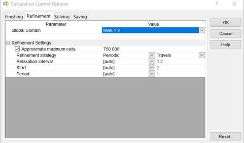
Figure 3: Calculation control settings for mesh refinement
Refinement Strategy: Flow Simulation offers 3 refinement strategies:
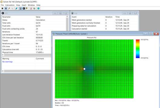
Figure 4: Manual mesh refinement for advanced control
(Hammer icon highlighted in red)
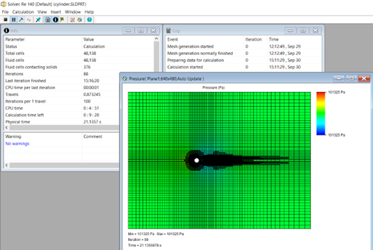
Figure 5: Mesh around the cylinder after 2 levels of manual refinement
(Observe the increase in the number of cells from Figure 4 to Figure 5 Highlighted in the blue box)

Figure 6: Pressure plot after solution adaptive mesh refinement
Visualizing the Impact:
Understanding the impact of adaptive meshing is crucial for gaining insights into simulation accuracy. SOLIDWORKS Flow Simulation provides several tools to facilitate this:
Conclusion
Adaptive meshing in SOLIDWORKS Flow Simulation is a significant advancement in fluid and gas simulations. This dynamic process, customizable and efficient, offers accurate results in less time. Whether for electronics cooling, piping systems, or complex automotive components, solution-adaptive meshing transforms your simulation workflow. It ensures accurate refinement where needed, improving designs and product reliability. Understanding its visual impact empowers users to make informed decisions and achieve simulation accuracy.
We Urge You To Call Us For Any Doubts & Clarifications That You May Have. We Are Eager to Talk To You
Call Us: +91 7406663589
 (No Ratings Yet)
#365/8, Ground Floor, "Hasmitha Avenue", 16th Main, 4th T Block East, Jayanagar, 4th T Block East, Pattabhirama Nagar, Jayanagar, Bengaluru, Karnataka 560041
Rated 4.7/5 with a total of 62 reviews
"CARAX" Building 4th Floor, 105/1/1/4, Next to Radha Hotel, Pune-Mumbai Xpress Way,Baner,Pune 411045
Rated 4.7/5 with a total of 17 reviews
1002, LODHA Supremus, I-Think Techno Campus,Kanjurmarg EAST - MUMBAI, MH, India – 400042.
Rated 5/5 with a total of 51 reviews
508, Shiti Ratna Complex, Panchwati Cross Road, Ahmedabad-380006
Rated 4.1/5 with a total of 7 reviews
Kanda's Villa, II Floor, AE Block,3362 R, 8th Street, Anna Nagar, Chennai, Tamil Nadu 600040
Rated 4.6/5 with a total of 16 reviews
Flat no F1, first floor, Nakhate corner, Eknath rang mandir road,New Usmanpura, Aurangabad, 431005.
A-101, 1st Floor, The Hub Complex, opp. Shete Hospital, Mahatma Nagar, Parijat Nagar, Nashik, Maharashtra 422005.
Level 7, Octave 3B Salarpuria Sattva Knowledge City, Inorbit Mall Road, Raidurg Village, Hi-tech City, Hyderabad, Telangana - 500081, India

pin up apk yukle https://azerbaijancuisine.com/# pin up az
pin up casino az
mexican drugstore online mexican northern doctors mexican mail order pharmacies
mexico drug stores pharmacies northern doctors mexico drug stores pharmacies
buying prescription drugs in mexico northern doctors pharmacy buying from online mexican pharmacy
mexican pharmaceuticals online mexican pharmacy northern doctors purple pharmacy mexico price list
http://northern-doctors.org/# buying from online mexican pharmacy
mexico pharmacies prescription drugs: mexican border pharmacies shipping to usa – mexican mail order pharmacies
https://northern-doctors.org/# mexican online pharmacies prescription drugs
http://northern-doctors.org/# best online pharmacies in mexico
mexican mail order pharmacies mexican pharmacy northern doctors buying prescription drugs in mexico
mexico drug stores pharmacies: mexican northern doctors – mexican rx online
http://northern-doctors.org/# mexican drugstore online
mexican online pharmacies prescription drugs: mexican pharmacy online – buying from online mexican pharmacy
mexican border pharmacies shipping to usa: mexican border pharmacies shipping to usa – buying prescription drugs in mexico
https://northern-doctors.org/# pharmacies in mexico that ship to usa
medication from mexico pharmacy: mexican pharmacy – best online pharmacies in mexico
reputable mexican pharmacies online: mexican pharmacy northern doctors – pharmacies in mexico that ship to usa
https://northern-doctors.org/# mexican drugstore online
medication from mexico pharmacy: purple pharmacy mexico price list – buying prescription drugs in mexico
mexico drug stores pharmacies northern doctors pharmacy medicine in mexico pharmacies
https://northern-doctors.org/# mexico drug stores pharmacies
mexican rx online: Mexico pharmacy that ship to usa – mexican border pharmacies shipping to usa
buying from online mexican pharmacy: mexican northern doctors – mexico pharmacies prescription drugs
https://northern-doctors.org/# mexico pharmacies prescription drugs
medication from mexico pharmacy: northern doctors pharmacy – п»їbest mexican online pharmacies
mexican pharmaceuticals online: mexican pharmacy northern doctors – п»їbest mexican online pharmacies
https://northern-doctors.org/# mexico drug stores pharmacies
mexico pharmacy: mexican pharmacy northern doctors – buying prescription drugs in mexico online
http://northern-doctors.org/# reputable mexican pharmacies online
buying prescription drugs in mexico online northern doctors mexican pharmaceuticals online
mexican online pharmacies prescription drugs: п»їbest mexican online pharmacies – medication from mexico pharmacy
mexico pharmacies prescription drugs: mexican border pharmacies shipping to usa – buying prescription drugs in mexico
https://northern-doctors.org/# mexican pharmaceuticals online
buying from online mexican pharmacy: northern doctors – best online pharmacies in mexico
https://northern-doctors.org/# pharmacies in mexico that ship to usa
mexican mail order pharmacies: northern doctors – mexican pharmaceuticals online
https://cmqpharma.online/# medicine in mexico pharmacies
mexico pharmacies prescription drugs
pharmacies in mexico that ship to usa buying from online mexican pharmacy mexican pharmaceuticals online
pharmacies in mexico that ship to usa: cmq mexican pharmacy online – mexican pharmacy
mexican rx online cmq pharma medicine in mexico pharmacies
buying from online mexican pharmacy mexican online pharmacy mexico drug stores pharmacies
buying prescription drugs in mexico online mexican pharmacy mexico pharmacies prescription drugs
purple pharmacy mexico price list
http://cmqpharma.com/# buying prescription drugs in mexico online
medication from mexico pharmacy
medication from mexico pharmacy mexican pharmacy mexico drug stores pharmacies
medication from mexico pharmacy online mexican pharmacy medication from mexico pharmacy
medication from mexico pharmacy purple pharmacy mexico price list best online pharmacies in mexico
reputable mexican pharmacies online buying from online mexican pharmacy pharmacies in mexico that ship to usa
india pharmacy mail order india pharmacy mail order reputable indian online pharmacy
https://canadapharmast.online/# canadian drug prices
medicine in mexico pharmacies buying prescription drugs in mexico mexican pharmacy
http://indiapharmast.com/# indianpharmacy com
buying from online mexican pharmacy mexican drugstore online mexican pharmacy
buying from online mexican pharmacy medication from mexico pharmacy pharmacies in mexico that ship to usa
https://foruspharma.com/# mexican drugstore online
where can i buy amoxicillin online: amoxicillin from canada – where can i buy amoxicillin over the counter
buy cipro no rx: antibiotics cipro – cipro 500mg best prices
doxycycline cap 50mg: 200 mg doxycycline – doxycycline hyc 100mg
doxycycline 150mg pill: doxycycline otc drug – doxycycline prices
paxlovid pill: paxlovid covid – paxlovid for sale
paxlovid pill: paxlovid for sale – paxlovid for sale
paxlovid buy: paxlovid pharmacy – п»їpaxlovid
can you buy amoxicillin over the counter canada: amoxicillin price without insurance – amoxicillin over counter
buying prescription drugs in mexico online pharmacies in mexico that ship to usa mexico pharmacies prescription drugs
https://mexicandeliverypharma.com/# purple pharmacy mexico price list
mexican online pharmacies prescription drugs: mexican pharmaceuticals online – reputable mexican pharmacies online
mexican pharmaceuticals online: mexico pharmacies prescription drugs – buying prescription drugs in mexico
mexican border pharmacies shipping to usa mexican rx online purple pharmacy mexico price list
purple pharmacy mexico price list: buying prescription drugs in mexico – purple pharmacy mexico price list
mexico pharmacies prescription drugs: buying from online mexican pharmacy – mexican border pharmacies shipping to usa
http://mexicandeliverypharma.com/# mexican border pharmacies shipping to usa
mexico pharmacies prescription drugs buying prescription drugs in mexico online buying prescription drugs in mexico
reputable mexican pharmacies online: mexico pharmacies prescription drugs – mexican pharmaceuticals online
medication from mexico pharmacy: purple pharmacy mexico price list – mexico drug stores pharmacies
https://mexicandeliverypharma.online/# buying prescription drugs in mexico online
mexican online pharmacies prescription drugs: mexican pharmaceuticals online – mexican online pharmacies prescription drugs
mexican rx online medication from mexico pharmacy mexican drugstore online
mexico pharmacies prescription drugs: purple pharmacy mexico price list – mexico pharmacies prescription drugs
mexican rx online: pharmacies in mexico that ship to usa – medication from mexico pharmacy
reputable mexican pharmacies online: п»їbest mexican online pharmacies – pharmacies in mexico that ship to usa
reputable mexican pharmacies online п»їbest mexican online pharmacies mexican drugstore online
п»їbest mexican online pharmacies: mexican rx online – п»їbest mexican online pharmacies
medication from mexico pharmacy: medicine in mexico pharmacies – п»їbest mexican online pharmacies
mexico drug stores pharmacies: mexican online pharmacies prescription drugs – buying prescription drugs in mexico online
buying from online mexican pharmacy mexican pharmaceuticals online reputable mexican pharmacies online
medication from mexico pharmacy: purple pharmacy mexico price list – mexican online pharmacies prescription drugs
reputable mexican pharmacies online: mexico drug stores pharmacies – mexican drugstore online
medication from mexico pharmacy: п»їbest mexican online pharmacies – best online pharmacies in mexico
mexico pharmacies prescription drugs reputable mexican pharmacies online medicine in mexico pharmacies
mexican online pharmacies prescription drugs: mexico pharmacies prescription drugs – pharmacies in mexico that ship to usa
mexico pharmacies prescription drugs: medication from mexico pharmacy – mexican drugstore online
buying prescription drugs in mexico online mexican drugstore online purple pharmacy mexico price list
purple pharmacy mexico price list: pharmacies in mexico that ship to usa – mexican border pharmacies shipping to usa
mexico drug stores pharmacies: buying prescription drugs in mexico online – mexican pharmaceuticals online
mexican mail order pharmacies: best online pharmacies in mexico – mexican online pharmacies prescription drugs
pharmacies in mexico that ship to usa mexico pharmacies prescription drugs mexico drug stores pharmacies
best online pharmacies in mexico: purple pharmacy mexico price list – mexican rx online
reputable mexican pharmacies online: mexican pharmaceuticals online – mexican border pharmacies shipping to usa
mexico drug stores pharmacies: mexican border pharmacies shipping to usa – mexican drugstore online
mexico pharmacies prescription drugs mexico drug stores pharmacies buying from online mexican pharmacy
pharmacies in mexico that ship to usa: purple pharmacy mexico price list – mexico drug stores pharmacies
best online pharmacies in mexico: buying prescription drugs in mexico – buying from online mexican pharmacy
best online pharmacies in mexico: mexican drugstore online – mexican drugstore online
buying prescription drugs in mexico online pharmacies in mexico that ship to usa mexico pharmacies prescription drugs
purple pharmacy mexico price list: buying prescription drugs in mexico online – buying prescription drugs in mexico online
buying prescription drugs in mexico: mexican border pharmacies shipping to usa – mexican online pharmacies prescription drugs
mexican drugstore online: mexico pharmacies prescription drugs – mexican mail order pharmacies
medication from mexico pharmacy mexico pharmacy purple pharmacy mexico price list
best online pharmacies in mexico: mexican online pharmacies prescription drugs – mexican pharmaceuticals online
mexico pharmacies prescription drugs: buying prescription drugs in mexico online – best online pharmacies in mexico
mexican mail order pharmacies: mexico drug stores pharmacies – mexican border pharmacies shipping to usa
buying from online mexican pharmacy mexican online pharmacies prescription drugs purple pharmacy mexico price list
purple pharmacy mexico price list: reputable mexican pharmacies online – buying prescription drugs in mexico
reputable mexican pharmacies online: reputable mexican pharmacies online – п»їbest mexican online pharmacies
mexican pharmaceuticals online: mexican pharmaceuticals online – mexico drug stores pharmacies
purple pharmacy mexico price list mexican pharmaceuticals online mexican pharmaceuticals online
buying prescription drugs in mexico: buying from online mexican pharmacy – mexican rx online
mexican mail order pharmacies: medication from mexico pharmacy – mexican drugstore online
pharmacies in mexico that ship to usa: mexican pharmaceuticals online – mexico drug stores pharmacies
mexico pharmacies prescription drugs best online pharmacies in mexico buying prescription drugs in mexico online
mexican pharmaceuticals online: best online pharmacies in mexico – buying prescription drugs in mexico online
buying from online mexican pharmacy: mexico drug stores pharmacies – mexican drugstore online
medication from mexico pharmacy: mexican pharmaceuticals online – п»їbest mexican online pharmacies
mexican pharmaceuticals online buying prescription drugs in mexico online mexico drug stores pharmacies
pharmacies in mexico that ship to usa: mexico drug stores pharmacies – reputable mexican pharmacies online
mexican pharmaceuticals online: medication from mexico pharmacy – п»їbest mexican online pharmacies
purple pharmacy mexico price list: buying from online mexican pharmacy – buying from online mexican pharmacy
mexican rx online mexican pharmaceuticals online mexican online pharmacies prescription drugs
reputable mexican pharmacies online: buying from online mexican pharmacy – mexican rx online
п»їbest mexican online pharmacies: reputable mexican pharmacies online – medicine in mexico pharmacies
mexican drugstore online: medication from mexico pharmacy – buying from online mexican pharmacy
mexican rx online п»їbest mexican online pharmacies mexico drug stores pharmacies
mexican mail order pharmacies: mexico pharmacies prescription drugs – mexican online pharmacies prescription drugs
medication from mexico pharmacy: mexico pharmacies prescription drugs – best online pharmacies in mexico
mexican border pharmacies shipping to usa: mexican rx online – mexican rx online
zithromax 500mg price zithromax 500 tablet zithromax generic price
aromatase inhibitor tamoxifen: effexor and tamoxifen – nolvadex steroids
http://prednisonebestprice.pro/# buy prednisone with paypal canada
http://zithromaxbestprice.pro/# where can i purchase zithromax online
where can i buy zithromax capsules zithromax for sale online zithromax cost uk
zithromax 1000 mg pills: zithromax 1000 mg online – zithromax capsules price
https://propeciabestprice.pro/# buy generic propecia pill
http://propeciabestprice.pro/# buy propecia without a prescription
effexor and tamoxifen nolvadex price tamoxifen and weight loss
prednisone 0.5 mg: prednisone brand name in usa – generic prednisone online
http://propeciabestprice.pro/# order propecia without rx
http://zithromaxbestprice.pro/# zithromax 250 price
order cytotec online buy cytotec pills online cheap cytotec abortion pill
п»їcytotec pills online: buy cytotec pills – buy cytotec
In this case, Leicester is the favorite and Fulham is the underdog. Having this information at your disposal can help shape your bet. It’s possible that the match will end in a draw (tie) and we show this where it says Draw. The biggest football bet ever won came back in 2001 when Mick Gibbs, a roofer from Staffordshire, landed a £500,000 windfall after placing 30p on a bet with odds of 1.6 million to one. Each round of football fixtures can be tipped in the OLBG football tipping competitions To get -115 odds on over 2.5 goals doesn’t really make sense, especially since this meeting was 3-2 the first time. Sure, it’s two teams that have struggled to score at times this season, but Leeds are allowing goals to everyone and it wouldn’t be surprising if Fulham scored three themselves.
https://lombok-directory.com/listings12737491/chandler-hooker-odds
Download Eminem Ft. Rihanna Love The Way You Lie mp3 song On today’s episode of Throw Back Thursday (TBT) we take y’all back to the super se… Bettors are probably not strange with this content, which provides trustworthy statistics and information for football pre-matches, allowing them to place more informed and accurate bets. Betimate always creates detailed match previews with comprehensive stats and analysis to help readers make more informed betting decisions. Our Twitter account not only offers live updates on the latest over 2.5 goals predictions but other sports betting tips too. For all this plus a healthy dose of sporting news and humour, follow us at @FootySuperTips. Are you looking for well-analyzed and sure Jackpot predictions based only on stats today? Look no further; Betwinner360 is here to offer you sure jackpot predictions and tips. From Daily jackpot and Midweek jackpot predictions this week to Mega jackpot predictions over the weekend. We have got you covered for sure jackpot predictions and tips this week.
buy tamoxifen: nolvadex 20mg – tamoxifen lawsuit
tamoxifen and weight loss: tamoxifen warning – nolvadex online
http://prednisonebestprice.pro/# prednisone 2.5 mg cost
prednisone online paypal: prednisone 20 tablet – prednisone ordering online
buying propecia without insurance: buy propecia prices – propecia
cost generic propecia without dr prescription: propecia without a prescription – cost of cheap propecia without a prescription
http://cytotecbestprice.pro/# Cytotec 200mcg price
how to get nolvadex: nolvadex for sale amazon – tamoxifen cyp2d6
tamoxifen brand name: tamoxifen buy – tamoxifen citrate
Farmacia online piГ№ conveniente: kamagra – farmacie online autorizzate elenco
le migliori pillole per l’erezione: acquisto viagra – viagra generico recensioni
comprare farmaci online all’estero: Farmacie che vendono Cialis senza ricetta – farmacia online
acquistare farmaci senza ricetta: Cialis generico 20 mg 8 compresse prezzo – top farmacia online
http://avanafil.pro/# farmaci senza ricetta elenco
farmacia online senza ricetta: Farmacie che vendono Cialis senza ricetta – Farmacia online miglior prezzo
farmacie online affidabili: Avanafil 50 mg – Farmacia online piГ№ conveniente
farmacie online affidabili: Cialis generico 20 mg 8 compresse prezzo – farmacie online affidabili
Farmacie online sicure: Avanafil a cosa serve – farmacie online sicure
http://kamagrait.pro/# farmaci senza ricetta elenco
farmacie online affidabili: kamagra oral jelly – acquistare farmaci senza ricetta
top farmacia online: acquistare farmaci senza ricetta – farmacie online affidabili
farmacia online senza ricetta: kamagra – farmaci senza ricetta elenco
https://viagragenerico.site/# cerco viagra a buon prezzo
Farmacie online sicure: super kamagra – acquistare farmaci senza ricetta
cialis 5mg daily how long before it works: Generic Cialis without a doctor prescription – generic cialis 7days
https://sildenafil.llc/# viagra generic
п»їover the counter viagra: buy sildenafil online usa – generic viagra overnight
http://sildenafil.llc/# over the counter alternative to viagra
viagra cialis sample pack: Buy Tadalafil 20mg – cialis overnight shipping
mastercard generic cialis: Buy Tadalafil 20mg – cialis online melbourne
https://tadalafil.auction/# cialis generic canada pharmacy
https://edpillpharmacy.store/# cheap ed meds
cheap erection pills
https://edpillpharmacy.store/# cheap ed
http://mexicopharmacy.win/# mexican online pharmacies prescription drugs
ed online meds
cheapest online pharmacy india: Indian pharmacy online – best india pharmacy
https://mexicopharmacy.win/# pharmacies in mexico that ship to usa
https://mexicopharmacy.win/# best online pharmacies in mexico
ed online pharmacy
best online pharmacies in mexico: Best pharmacy in Mexico – mexican drugstore online
buying prescription drugs in mexico: mexican pharmacy – buying prescription drugs in mexico online
http://mexicopharmacy.win/# mexico drug stores pharmacies
Online medicine home delivery: Online pharmacy – indian pharmacy paypal
http://indiapharmacy.shop/# indianpharmacy com
reputable indian online pharmacy: Best Indian pharmacy – indian pharmacy
india pharmacy: Online pharmacy – indian pharmacy
http://mexicopharmacy.win/# buying prescription drugs in mexico
erectile dysfunction pills for sale: online ed medicine – where can i get ed pills
indian pharmacy: indian pharmacy – indian pharmacy online
http://indiapharmacy.shop/# cheapest online pharmacy india
where to get ed pills: ed pills online – ed med online
https://mexicopharmacy.win/# mexico pharmacies prescription drugs
cheapest online pharmacy india: Top online pharmacy in India – indian pharmacy paypal
best online ed pills: erection pills online – online ed meds
http://edpillpharmacy.store/# cheap ed pills online
mexican rx online: mexican pharmacy – best online pharmacies in mexico
http://edpillpharmacy.store/# what is the cheapest ed medication
п»їlegitimate online pharmacies india: Cheapest online pharmacy – best online pharmacy india
Online medicine home delivery: Online pharmacy USA – india pharmacy mail order
pharmacy website india: indian pharmacy – indian pharmacy paypal
п»їlegitimate online pharmacies india: indian pharmacy – world pharmacy india
erectile dysfunction online prescription: ED meds online with insurance – order ed pills online
online shopping pharmacy india: Top online pharmacy in India – buy prescription drugs from india
2024-25 NFL Offensive Player of the Year Award Odds: Good Luck Taming ‘Cheetah’ Every day we select one or two bets from our experienced tipsters’ predictions to give as the bet of the day, the matches we think has the best chance of winning. Not only do we look for bets that have a good chance of winning, we also look for value to get you the best possible return. Top Football Predictions Today This website is using a security service to protect itself from online attacks. The action you just performed triggered the security solution. There are several actions that could trigger this block including submitting a certain word or phrase, a SQL command or malformed data. Football prediction is a complex of knowledge, experience, and of course, luck. We only wish that there were surefire win forecasts but even the most likely of predictions can go wrong. Erling Haaland doesn’t score in every game and must win teams often only draw or even lose. While there may not be a guarantee of sure win football tips and predictions, there are certainly actions you can take to increase your chances. Continue reading below for some tips and strategies on how to get your football bets as close to a sure bet prediction as possible!
https://fab-directory.com/listings12795424/boylesports-horse-racing-betting
Opposite of laying the points is taking the points, which is a point-spread bet on the underdog. Betting on a 7.5-point underdog would be called taking the points, and the team would need to lose by seven points or less (or win). The Argos averaged 32.8 ppg last year but their team total is set at 20.5 at most books due to the nine-game suspension of reigning MOP Chad Kelly. While they’ll miss Kelly at QB, this is a massive overreaction given how well Cameron Dukes has played in limited snaps behind the league’s best line. He made two starts in 2023, completing 17-of-24 passes for 231 yards against a tough Winnipeg defense on the road in Week 17 and torching Ottawa for 317 yards in the regular season finale. He also went 14-18 for 180 yards in the preseason. BC allowed 30.9 ppg in the final 11 regular season and playoff games last year and could be even worse on that side of the ball after losing a few key defenders.
buy cytotec over the counter https://furosemide.win/# lasix 40 mg
lasix tablet
medicine lisinopril 10 mg: Buy Lisinopril 20 mg online – how to buy lisinopril online
lisinopril 2.5 mg buy online cheap lisinopril lisinopril 30 mg daily
https://lipitor.guru/# lipitor 10mg tablets
generic lasix: lasix generic name – lasix medication
buy cytotec over the counter https://cytotec.pro/# buy cytotec pills online cheap
lasix 100 mg
buy cytotec online fast delivery cheapest cytotec purchase cytotec
https://cytotec.pro/# cytotec online
buy cytotec pills online cheap: buy misoprostol tablet – buy cytotec online
Abortion pills online http://cytotec.pro/# buy cytotec over the counter
lasix pills
https://furosemide.win/# buy furosemide online
tamoxifen endometriosis buy tamoxifen citrate tamoxifen dosage
buy cytotec pills online cheap http://lipitor.guru/# lipitor generic australia
buy lasix online
lipitor 40 mg price in india: Atorvastatin 20 mg buy online – lipitor price in canada
https://lisinopril.guru/# lisinopril 30 mg daily
Misoprostol 200 mg buy online https://furosemide.win/# furosemide
lasix 40 mg
tamoxifen bone pain: buy tamoxifen citrate – nolvadex pills
femara vs tamoxifen: nolvadex estrogen blocker – should i take tamoxifen
http://tamoxifen.bid/# arimidex vs tamoxifen bodybuilding
cytotec buy online usa http://lisinopril.guru/# prinivil 10 mg
furosemide
lipitor cost: buy atorvastatin online – lipitor 10 mg tablet price
https://lisinopril.guru/# lisinopril without an rx
buy lisinopril 40 mg online: Lisinopril online prescription – zestril 10 mg in india
п»їcytotec pills online https://cytotec.pro/# buy misoprostol over the counter
lasix furosemide 40 mg
generic tamoxifen: buy tamoxifen citrate – benefits of tamoxifen
tamoxifen: buy tamoxifen citrate – generic tamoxifen
buy cytotec https://lipitor.guru/# lipitor online pharmacy
lasix 20 mg
order cytotec online: buy misoprostol tablet – buy cytotec
generic lipitor price: Lipitor 10 mg price – lipitor price drop
buy cytotec online https://cytotec.pro/# buy cytotec
lasix
cytotec abortion pill: cheapest cytotec – buy misoprostol over the counter
tamoxifen for gynecomastia reviews: Purchase Nolvadex Online – arimidex vs tamoxifen bodybuilding
cytotec online http://tamoxifen.bid/# effexor and tamoxifen
furosemide 100mg
aromatase inhibitor tamoxifen: nolvadex pct – raloxifene vs tamoxifen
top online pharmacy india mail order pharmacy india indian pharmacy online
best online pharmacies in mexico: buying from online mexican pharmacy – mexican online pharmacies prescription drugs
https://easyrxcanada.com/# reputable canadian online pharmacy
http://easyrxindia.com/# top 10 online pharmacy in india
mexican drugstore online mexico drug stores pharmacies buying prescription drugs in mexico online
https://easyrxcanada.com/# pharmacy wholesalers canada
http://easyrxindia.com/# reputable indian pharmacies
п»їlegitimate online pharmacies india: Online medicine order – cheapest online pharmacy india
best india pharmacy Online medicine order indian pharmacy
https://easyrxindia.com/# Online medicine home delivery
best india pharmacy: buy prescription drugs from india – reputable indian pharmacies
https://mexstarpharma.com/# best online pharmacies in mexico
canadian king pharmacy: canadian mail order pharmacy – buying drugs from canada
mexican online pharmacies prescription drugs: medicine in mexico pharmacies – mexican border pharmacies shipping to usa
http://easyrxindia.com/# indian pharmacies safe
canadianpharmacyworld: legal canadian pharmacy online – safe canadian pharmacy
http://easyrxindia.com/# buy medicines online in india
https://easyrxcanada.online/# northwest pharmacy canada
guvenilir slot siteleri: guvenilir slot siteleri – guvenilir slot siteleri
slot oyun siteleri: en cok kazandiran slot siteleri – yasal slot siteleri
slot kumar siteleri: slot siteleri 2024 – slot siteleri 2024
http://slotsiteleri.bid/# 2024 en iyi slot siteleri
sweet bonanza demo: sweet bonanza demo – sweet bonanza giris
en iyi slot siteler: en guvenilir slot siteleri – deneme veren slot siteleri
https://denemebonusuverensiteler.win/# deneme bonusu veren siteler
http://slotsiteleri.bid/# slot bahis siteleri
slot bahis siteleri: deneme bonusu veren siteler – yeni slot siteleri
canl? slot siteleri: guvenilir slot siteleri – guvenilir slot siteleri
Wow, incredible blog layout! How long have you been blogging for? you made blogging look easy. The overall look of your website is fantastic, as well as the content!
guvenilir slot siteleri: deneme veren slot siteleri – slot oyun siteleri
https://denemebonusuverensiteler.win/# bonus veren siteler
pin up казино: пин ап казино вход – пин ап вход
pin up: pin up casino – пин ап вход
http://1xbet.contact/# 1xbet зеркало
вавада зеркало: вавада – вавада казино
pin up casino: pin up – пин ап зеркало
ван вин 1win зеркало 1win вход
https://pin-up.diy/# пин ап
1вин: 1вин – 1вин
пин ап зеркало: пин ап зеркало – pin up casino
пин ап казино вход: пин ап зеркало – pin up
https://1win.directory/# 1win зеркало
vavada: vavada казино – вавада
http://pin-up.diy/# pin up казино
pin up казино: pin up casino – пин ап вход
1хбет зеркало: 1хбет – 1хбет официальный сайт
http://vavada.auction/# вавада рабочее зеркало
Es importante destacar que los casinos online en Perú están regulados y operan legalmente, lo que significa que los jugadores pueden confiar en que están jugando en un entorno seguro y justo. Además, los casinos online en este país se toman en serio el juego responsable y ofrecen herramientas para ayudar a los jugadores a mantener el control de su actividad de juego. Los casinos que obtuvieron una puntuación alta en todos los items del listado en mención son MostBet Casino y Casimba Casino. Ambos operadores tienen una una sala de juegos con una gran librería de tragamonedas y casino online en vivo. Los casinos online con dinero real son los que ofrecen pagos rápidos a los jugadores en una moneda válida que pueden utilizar fuera de la plataforma de juego. Esto quiere decir que los jugadores que depositan, o hasta los que no depositan, pueden obtener dinero real después de jugar. Para saber si el casino en el que quieres jugar te da la opción de ganar dinero real, debes entrar en su página de bonos de casino y leer sus términos y condiciones.
https://app.pluralsight.com/profile/dornbrook-epifano
Dentro de los casinos existen varias alternativas y versiones del juego. Las más populares son la ruleta francesa y la ruleta europea. De hecho, son dos opciones que se parecen bastante. Ambas cuentan con un solo 0 y 36 números divididos equitativamente entre el color rojo y el negro. Ahora bien, es habitual que la plataforma disponga de una ruleta simulador. Por eso, los jugadores que prefieren la ruleta francesa pueden buscar el simulador ruleta francesa. Si crees que las herramientas disponibles no funcionan de forma efectiva contigo y quieres dejar de jugar completamente, entonces la mejor opción es la auto-exclusión. Si te auto-excluyes de jugar en William Hill, te cerraremos tu cuenta por un periodo específico de entre 6 meses y 5 años, y a menos que nos contactes después de que el periodo de auto-exclusión haya acabado, no reabriremos tu cuenta. Tras acabar tu periodo de auto-exclusión y si consideras que ya tienes control de tu juego y que puedes abrir de nuevo tu cuenta, tienes que contactar con atención al cliente. Se te aplicará un periodo de reflexión de 24 h y durante este periodo podrás reconsiderar tu decisión.
https://onlineph24.com/# Endep
discount pharmacy viagra
kaiser pharmacy hours: publix pharmacy free lisinopril – how to start a pharmacy store
https://drstore24.com/# testosterone gel online pharmacy
doxycycline online pharmacy no prescription
tadacip online pharmacy: ambien india pharmacy – kroger pharmacy fluoxetine
https://pharm24on.com/# cheap erectile dysfunction pills online
river pharmacy revia
clozapine registry pharmacy: effexor online pharmacy – warfarin pharmacy protocol
simvastatin pharmacy prices: mexican online mail order pharmacy – pharmacy viagra prices
https://drstore24.com/# xeloda specialty pharmacy alliance
skelaxin prices pharmacy
abdulhay ali ahmed alawadhiand bahrain pharmacy & general store: tretinoin cream pharmacy – can i buy viagra at a pharmacy
online pharmacy overnight delivery: pharmacy direct cialis – online pharmacy weight loss
online pharmacy xenical: pharmacy ce online – fanda pharmacy hong kong cialis
prices pharmacy: buy naltrexone from trusted pharmacy – diovan pharmacy
online pharmacy fedex overnight shipping: gold pharmacy online – dapoxetine online pharmacy
online shopping pharmacy india indian pharmacy Online medicine home delivery
buspirone pharmacy: terbinafine target pharmacy – legitimate mexican pharmacy online
pharmacies in mexico that ship to usa: mexican online pharmacies prescription drugs – mexico pharmacies prescription drugs
https://indianpharmacy.company/# india pharmacy mail order
zoloft pharmacy prices: ventolin uk pharmacy – best online propecia pharmacy
rx city pharmacy: cetirizine pharmacy – amoxicillin from pharmacy
http://mexicopharmacy.cheap/# buying prescription drugs in mexico online
finasteride online pharmacy india tamoxifen pharmacy Vermox
world pharmacy india: indianpharmacy com – п»їlegitimate online pharmacies india
Raw Trading Ltd registered in Seychelles with registration number: 8419879-2, is regulated by the Financial Services Authority of Seychelles with License number: SD018.Risk Warning: Trading Derivatives carries a high level of risk to your capital, and you should only trade with money you can afford to lose. Trading Derivatives may not be suitable for all investors, so please ensure that you fully understand the risks involved and seek independent advice if necessary. Moreover, with competitive spreads and low trading commissions, Tickmill enables traders to capitalize on the volatility of the cryptocurrency markets efficiently. Additionally, Tickmill‘s cryptocurrency trading features include access to advanced trading platforms like MetaTrader 4 and MetaTrader 5, equipped with comprehensive charting tools, technical indicators, and expert advisors.
https://kyleriezt303306.blog2learn.com/77751913/fintechzoom-best-forex-broker-2024
So far you have read about Forex and stock trading, and now it’s your final call as to whether trade or not. But always consider the right trading infrastructure and platforms that MilesWeb offers. With their higher SSD NVMe storage and unmetered bandwidth, traders will not get speed or trading performance issues. Besides, 24×7 technical support from MilesWeb is always there to answer queries. Solead is the Best Blog & Magazine WordPress Theme with tons of customizations and demos ready to import, illo inventore veritatis et quasi architecto. The queen of forex demons, Euphoria, is a creature that promises unlimited wealth, and delivers unlimited misery and destitution. Euphoria works hard to ensure that wherever we look, we see nothing but wonderful prospects for limitless profits. It is as if the trader has somehow been blessed with the Midas Touch, with success being the natural consequence of their routine behavior.
blood pressure: Cozaar – french pharmacy online store
best online pharmacy advair viagra online pharmacy us no prescription pharmacy paypal
generic cialis us pharmacy: mint rx pharmacy – jcm pharmacy tadacip
http://pharmbig24.com/# revia online pharmacy
top online pharmacy india: mail order pharmacy india – top 10 pharmacies in india
mexican mail order pharmacies pharmacies in mexico that ship to usa mexico drug stores pharmacies
indian pharmacy: Online medicine order – top online pharmacy india
https://mexicopharmacy.cheap/# buying prescription drugs in mexico
rx pharmacy coupons reviews rx pharmacy discount card pharmacy online clomid
complete online pharmacy: mebendazole pharmacy – renova mexico pharmacy
viagra us pharmacy: save rx discount pharmacy – how much does viagra cost at a pharmacy
india online pharmacy reputable indian online pharmacy world pharmacy india
Online medicine order: indianpharmacy com – pharmacy website india
https://pharmbig24.online/# pharmacy dispensing clozaril
coumadin pharmacy: priligy in malaysia+pharmacy – best online pharmacy clomid
indian pharmacy: mail order pharmacy india – india online pharmacy
best india pharmacy indianpharmacy com online pharmacy india
Whoa! This blog looks exactly like my old one! It’s on a completely different topic but it has pretty much the same page layout and design. Excellent choice of colors!
http://indianpharmacy.company/# buy prescription drugs from india
wellbutrin xl pharmacy: big pharmacy online – united kingdom online pharmacy
buying prescription drugs in mexico online mexican border pharmacies shipping to usa pharmacies in mexico that ship to usa
Online medicine home delivery: buy medicines online in india – india pharmacy
Online medicine order top online pharmacy india indianpharmacy com
Online medicine order: best india pharmacy – top 10 pharmacies in india
https://pharmbig24.online/# tesco pharmacy sildenafil
mail order pharmacy india: buy medicines online in india – mail order pharmacy india
target pharmacy omeprazole dexamethasone pharmacy clindamycin online pharmacy
Hey there, You’ve done a great job. I will certainly digg it and personally recommend to my friends. I’m sure they’ll be benefited from this website.
top 10 online pharmacy in india: mail order pharmacy india – top 10 online pharmacy in india
https://indianpharmacy.company/# india pharmacy mail order
medicine in mexico pharmacies: mexican online pharmacies prescription drugs – п»їbest mexican online pharmacies
online pharmacy viagra generic people’s pharmacy lisinopril can i buy viagra at pharmacy
russian pharmacy online: flomax pharmacy questionnaire – french pharmacy products online
world pharmacy india: indian pharmacy – reputable indian pharmacies
online pharmacy india india pharmacy indian pharmacy
pharmacy choice cetirizine: inhouse pharmacy finpecia – inhouse pharmacy finpecia
cheapest online pharmacy india world pharmacy india п»їlegitimate online pharmacies india
betine guncel betine giris betine guncel
starz bet giris starzbet giris starzbet guncel giris
https://starzbet.shop/# starz bet giris
casibom giris casibom giris casibom
http://starzbet.shop/# starzbet guvenilir mi
http://betine.online/# betine sikayet
gates of olympus turkce gates of olympus demo turkce oyna gates of olympus demo oyna
https://gatesofolympusoyna.online/# gate of olympus oyna
betine promosyon kodu betine giris betine guncel
https://farmaciaeu.com/# farmacia online barcelona
farmacia online envГo gratis: farmacias online seguras – farmacia online madrid
farmacia online espaГ±a envГo internacional farmacia online envio gratis valencia farmacias online seguras en espaГ±a
farmacias direct: Cialis precio – farmacia online 24 horas
farmacias online seguras: cialis 20 mg precio farmacia – farmacia barata
https://tadalafilo.bid/# п»їfarmacia online espaГ±a
farmacias online seguras en espaГ±a cialis en Espana sin receta contrareembolso farmacias online seguras en espaГ±a
viagra online cerca de la coruГ±a: sildenafilo 50 mg precio sin receta – venta de viagra a domicilio
http://farmaciaeu.com/# farmacia online barcelona
farmacia online envГo gratis
http://farmaciaeu.com/# farmacias online seguras
sildenafilo 50 mg comprar online: comprar viagra en espana – se puede comprar sildenafil sin receta
п»їfarmacia online espaГ±a: farmacia 24 horas – farmacias online seguras en espaГ±a
https://sildenafilo.men/# viagra online cerca de toledo
п»їfarmacia online espaГ±a: farmacia online madrid – farmacias online seguras
Cross-Platform: Time is a very important component in trading, so trading applications are created to enable users to connect to their app in seconds on various media platforms. These may be utilised on iOS and Android platforms, giving consumers access to their software at any location or device. 5. AMarkets: An established ECN broker offering fast order execution speeds, low market spreads, and a proprietary laboratory for algorithmic trading. They also provide a compensation fund of up to EUR 20,000 per client and a new passive investment platform. However, their high minimum deposit and offshore regulation could be potential drawbacks, and it’s recommended to test expert advisors before launching them. For CFD share trading, the broker presents a selection of platforms, including both MetaTrader 4 and their sophisticated NGEN platform. Furthermore, the commission rates are transparent and competitive, dropping to as low as 0.04% for shares on the ASX market. With CMC Markets, we traded UK shares at a 0.08% commission and US shares at .02 cents per unit.
https://www.soulsisterdecorating.com/forum/general-discussions/online-forex-broker-reviews-and-ratings
Forex trading is a global marketplace where currencies are bought and sold, and India has its burgeoning community of traders. If you’re looking to dive into this exciting financial world, here’s a step-by-step guide to get you started. While it may differ from one broker to another, the capital required to open a currency trading is minimal. You can check with the broker of your choice to find out how much deposit they require for you to start trading in currencies. Furthermore, forex traders have been known to use several different strategies to get the best out of the futures or options positions. That’s why the question of “how to start forex trading” can have many answers. The trader’s goal is to predict changes in the price of their chosen asset and make a transaction at the right time. To do this, requires learning the different factors that may influence trends, knowing how to analyze the market environment, and a lot of practice.
https://sildenafilo.men/# sildenafilo 100mg precio farmacia
farmacia online envГo gratis
https://tadalafilo.bid/# farmacias online seguras en espaГ±a
п»їViagra online cerca de Madrid: sildenafilo – se puede comprar viagra sin receta
https://tadalafilit.com/# comprare farmaci online con ricetta
acquisto farmaci con ricetta
esiste il viagra generico in farmacia acquisto viagra miglior sito per comprare viagra online
viagra pfizer 25mg prezzo: viagra online siti sicuri – viagra consegna in 24 ore pagamento alla consegna
viagra naturale in farmacia senza ricetta: acquisto viagra – pillole per erezioni fortissime
Farmacie on line spedizione gratuita Cialis generico prezzo comprare farmaci online con ricetta
pillole per erezioni fortissime viagra farmacia pillole per erezioni fortissime
farmaci senza ricetta elenco: acquistare farmaci senza ricetta – Farmacia online miglior prezzo
le migliori pillole per l’erezione: viagra online spedizione gratuita – viagra online spedizione gratuita
http://farmaciait.men/# Farmacie on line spedizione gratuita
acquisto farmaci con ricetta
farmaci senza ricetta elenco Cialis generico recensioni farmacie online sicure
viagra pfizer 25mg prezzo: viagra farmacia – esiste il viagra generico in farmacia
migliori farmacie online 2024 Cialis generico prezzo comprare farmaci online all’estero
farmacia online: Cialis generico 5 mg prezzo – п»їFarmacia online migliore
Farmacie online sicure: Farmacie on line spedizione gratuita – Farmacie on line spedizione gratuita
acquisto farmaci con ricetta Cialis generico 20 mg 8 compresse prezzo farmacia online
http://tadalafilit.com/# Farmacie online sicure
acquisto farmaci con ricetta
farmacia online Farmacie on line spedizione gratuita comprare farmaci online all’estero
farmacia online: Farmacia online piu conveniente – top farmacia online
Farmacia online piГ№ conveniente: Cialis generico 5 mg prezzo – farmacie online autorizzate elenco
acquisto farmaci con ricetta Tadalafil generico migliore Farmacie online sicure
farmacie online affidabili Farmacie online sicure acquisto farmaci con ricetta
https://sildenafilit.pro/# viagra acquisto in contrassegno in italia
farmacie online sicure
Farmacia online miglior prezzo: BRUFEN 600 acquisto online – farmaci senza ricetta elenco
farmacie online affidabili Farmacie che vendono Cialis senza ricetta Farmacie on line spedizione gratuita
acquistare farmaci senza ricetta: Brufen antinfiammatorio – Farmacia online piГ№ conveniente
https://tadalafilit.com/# acquistare farmaci senza ricetta
farmacia online piГ№ conveniente
farmacia online piГ№ conveniente: Ibuprofene 600 prezzo senza ricetta – comprare farmaci online all’estero
Farmacie on line spedizione gratuita Brufen 600 prezzo migliori farmacie online 2024
comprare farmaci online all’estero BRUFEN 600 acquisto online farmacia online senza ricetta
Farmacie on line spedizione gratuita: farmacia online migliore – Farmacie on line spedizione gratuita
п»їFarmacia online migliore: Cialis generico 20 mg 8 compresse prezzo – migliori farmacie online 2024
http://tadalafilit.com/# farmacie online sicure
Farmacia online piГ№ conveniente
п»їFarmacia online migliore Cialis generico controindicazioni farmacia online senza ricetta
Farmacia online miglior prezzo Tadalafil generico migliore farmacia online
acquisto farmaci con ricetta: Farmacie online sicure – farmacie online affidabili
farmacia online senza ricetta Brufen 600 prezzo con ricetta farmacia online senza ricetta
farmacia online piГ№ conveniente: Cialis generico prezzo – п»їFarmacia online migliore
https://farmaciait.men/# farmacia online
farmacie online affidabili
farmacia online Farmacia online migliore Farmacie on line spedizione gratuita
farmacia online senza ricetta: BRUFEN 600 acquisto online – Farmacie online sicure
viagra naturale viagra generico viagra subito
http://furosemide.men/# lasix medication
ventolin pharmacy Ventolin inhaler best price how much is a ventolin
gabapentin buy: neurontin cream – prescription medication neurontin
ventolin order: Ventolin inhaler – ventolin inhaler without prescription
600 mg neurontin tablets: neurontin 1000 mg – can i buy neurontin over the counter
Buy compounded semaglutide online buy rybelsus Buy compounded semaglutide online
buy lasix online: buy furosemide – furosemide 40mg
http://rybelsus.tech/# cheap Rybelsus 14 mg
rybelsus generic: Rybelsus 7mg – Rybelsus 7mg
buy rybelsus: buy rybelsus – buy rybelsus
prednisone 20mg prescription cost: prednisone buy without prescription – prednisone 10
lasix pills: buy furosemide – lasix dosage
http://prednisolone.pro/# prednisone 10mg tablet price
lasix dosage: cheap lasix – lasix online
prednisone 300mg: prednisone buy canada – medicine prednisone 10mg
average cost of prednisone: prednisone 20 mg without prescription – prednisone best prices
prednisone 5 tablets: prednisone 20 mg pill – prednisone 10 mg tablet cost
https://furosemide.men/# lasix for sale
25 mg prednisone: prednisone 20mg tab price – can i purchase prednisone without a prescription
prednisone 20mg by mail order: prednisone 20mg price – prednisone 10mg tablets
lasix 20 mg: cheap lasix – furosemide 40 mg
safe online pharmacies in canada: Cheapest online pharmacy – safe canadian pharmacy
http://indiadrugs.pro/# cheapest online pharmacy india
Online medicine order Indian pharmacy online indian pharmacy paypal
reputable mexican pharmacies online: mexican online pharmacies prescription drugs – mexican drugstore online
canadian valley pharmacy: canadian pharmacy antibiotics – online canadian pharmacy review
https://canadapharma.shop/# online canadian pharmacy reviews
india online pharmacy online Indian pharmacy Online medicine home delivery
http://mexicanpharma.icu/# п»їbest mexican online pharmacies
online pharmacy canada: Online medication home delivery – canadian pharmacy meds reviews
http://canadapharma.shop/# canadian medications
canadian drugstore online: Canadian Pharmacy – canada drugstore pharmacy rx
mexico pharmacies prescription drugs medication from mexico medicine in mexico pharmacies
medicine in mexico pharmacies http://mexicanpharma.icu/# mexican rx online
purple pharmacy mexico price list
https://mexicanpharma.icu/# mexican drugstore online
top 10 pharmacies in india Online medication home delivery best online pharmacy india
https://indiadrugs.pro/# indian pharmacy online
I beloved up to you will receive carried out proper here. The caricature is attractive, your authored subject matter stylish. however, you command get bought an shakiness over that you wish be handing over the following. sick certainly come further in the past once more since exactly the same nearly very incessantly within case you defend this hike.
https://canadapharma.shop/# legal canadian pharmacy online
online pharmacy india Online medication home delivery india online pharmacy
mexico drug stores pharmacies: mexican pharmacy – pharmacies in mexico that ship to usa
best online pharmacies in mexico
mexico pharmacies prescription drugs: mexico drug stores pharmacies – mexico drug stores pharmacies
http://pharmaciepascher.pro/# pharmacie en ligne pas cher
Viagra gГ©nГ©rique sans ordonnance en pharmacie: viagra sans ordonnance – Viagra homme prix en pharmacie
pharmacie en ligne pas cher cialis generique pharmacie en ligne pas cher
http://pharmaciepascher.pro/# Pharmacie sans ordonnance
Viagra homme prix en pharmacie sans ordonnance: viagra en ligne – Viagra pas cher paris
Viagra homme prix en pharmacie: Viagra gГ©nГ©rique sans ordonnance en pharmacie – Viagra vente libre pays
Viagra gГ©nГ©rique sans ordonnance en pharmacie viagra sans ordonnance Viagra 100 mg sans ordonnance
Viagra 100mg prix: Viagra generique en pharmacie – Viagra 100 mg sans ordonnance
SildГ©nafil 100 mg prix en pharmacie en France: Viagra prix – SildГ©nafil Teva 100 mg acheter
pharmacie en ligne fiable pharmacies en ligne certifiГ©es acheter mГ©dicament en ligne sans ordonnance
https://vgrsansordonnance.com/# Viagra prix pharmacie paris
vente de mГ©dicament en ligne: Acheter Cialis – pharmacie en ligne livraison europe
Sildenafil teva 100 mg sans ordonnance: viagra en ligne – Viagra 100mg prix
Pharmacie en ligne livraison Europe vente de mГ©dicament en ligne pharmacie en ligne france pas cher
ozempic coupon ozempic online Ozempic without insurance
http://ozempic.art/# ozempic online
buy ozempic: buy ozempic pills online – buy ozempic
ozempic coupon: ozempic cost – ozempic cost
https://ozempic.art/# Ozempic without insurance
rybelsus cost semaglutide cost rybelsus cost
https://rybelsus.shop/# semaglutide cost
semaglutide online: semaglutide tablets – buy semaglutide online
semaglutide tablets buy semaglutide online rybelsus coupon
https://rybelsus.shop/# cheapest rybelsus pills
rybelsus cost: buy semaglutide online – semaglutide tablets
http://rybelsus.shop/# rybelsus pill
ozempic ozempic cost ozempic generic
https://ozempic.art/# ozempic coupon
buy semaglutide online: semaglutide cost – rybelsus cost
https://rybelsus.shop/# rybelsus pill
semaglutide online buy semaglutide pills buy semaglutide online
rybelsus coupon: buy rybelsus online – semaglutide cost
https://ozempic.art/# buy cheap ozempic
https://rybelsus.shop/# rybelsus coupon
ozempic ozempic online ozempic online
ozempic coupon: Ozempic without insurance – ozempic
https://ozempic.art/# Ozempic without insurance
https://ozempic.art/# ozempic
buy cheap ozempic buy ozempic pills online buy ozempic pills online
Ozempic without insurance: ozempic – ozempic cost
http://ozempic.art/# Ozempic without insurance
semaglutide tablets buy semaglutide pills buy semaglutide pills
https://rybelsus.shop/# rybelsus price
https://ozempic.art/# ozempic generic
rybelsus cost buy semaglutide pills buy rybelsus online
buy semaglutide pills: semaglutide online – rybelsus coupon
https://rybelsus.shop/# rybelsus coupon
http://rybelsus.shop/# buy rybelsus online
http://rybelsus.shop/# rybelsus pill
Ozempic without insurance ozempic buy ozempic pills online
rybelsus pill: buy semaglutide online – rybelsus pill
pin up azerbaijan pin up azerbaijan pin-up oyunu
pin up 306: pinup az – pin-up casino giris
https://pinupturkey.pro/# pin up guncel giris
pin up казино пин ап казино вход пин ап
pin up казино: pin up – пин ап 634
пин ап кз: pin up – пин ап
пин ап кз: пинап казино – pin up казино
pin up az pin up az pin up 306
pin up зеркало: пин ап казино – пинап казино
пинап казино: пинап казино – пин ап казино зеркало
https://pinupturkey.pro/# pin up aviator
pin-up oyunu pin up casino pin up azerbaijan
https://pinupkz.tech/# пинап казино
пин ап официальный сайт: пин ап казино вход – pin up зеркало
pin up 306 pin-up kazino pinup az
пинап кз: пинап казино – pin up kz
http://pinupaz.bid/# pin up 306
pin up казино пинап кз pin up kz
pinup azerbaycan: pin up az – pin-up oyunu
https://amoxil.llc/# amoxicillin for sale
buy zithromax online australia
https://gabapentin.auction/# medicine neurontin capsules
zithromax over the counter uk buy zithromax z-pak online zithromax 250 mg tablet price
ivermectin price usa: stromectol for sale – buy ivermectin canada
http://zithromax.company/# zithromax online usa
https://gabapentin.auction/# buying neurontin without a prescription
http://semaglutide.win/# semaglutide
zithromax online pharmacy canada
minocycline 50mg over the counter: order stromectol – cost of ivermectin pill
https://semaglutide.win/# semaglutide
where can i purchase zithromax online zithromax for sale zithromax 500mg
https://gabapentin.auction/# neurontin 200 mg capsules
http://stromectol.agency/# ivermectin oral 0 8
http://amoxil.llc/# azithromycin amoxicillin
zithromax cost australia
stromectol over the counter: stromectol for sale – stromectol 0.5 mg
https://gabapentin.auction/# neurontin price australia
buy neurontin order gabapentin neurontin drug
https://amoxil.llc/# buy amoxicillin online no prescription
zithromax for sale us
amoxicillin 500 mg without prescription: Amoxicillin For sale – amoxicillin 500mg pill
https://gabapentin.auction/# where to buy neurontin
https://gabapentin.auction/# how to get neurontin
zithromax online pharmacy canada order zithromax buy zithromax 1000 mg online
https://gabapentin.auction/# neurontin over the counter
zithromax 500 mg for sale
http://semaglutide.win/# Rybelsus 14 mg price
buy amoxicillin 500mg capsules uk: Amoxicillin For sale – generic amoxicillin 500mg
zithromax generic price zithromax best price zithromax 500mg over the counter
https://zithromax.company/# zithromax 1000 mg pills
https://amoxil.llc/# amoxicillin 500mg price
https://zithromax.company/# buy zithromax 1000 mg online
can i buy zithromax over the counter
buy rybelsus: cheap Rybelsus 14 mg – Rybelsus 14 mg price
minocycline 50mg without prescription cheapest stromectol stromectol uk
https://zithromax.company/# zithromax 500 mg for sale
I get pleasure from, lead to I discovered exactly what I was taking a look for. You’ve ended my 4 day lengthy hunt! God Bless you man. Have a great day. Bye
https://stromectol.agency/# stromectol online
buy cheap zithromax online
how to buy zithromax online: buy zithromax z-pak online – zithromax online usa no prescription
http://gabapentin.auction/# neurontin price in india
https://gabapentin.auction/# neurontin price in india
https://semaglutide.win/# Rybelsus 7mg
can you buy zithromax over the counter in australia
https://zithromax.company/# zithromax buy online
stromectol pill: order stromectol – cost for ivermectin 3mg
amoxicillin 500mg capsule Amoxicillin For sale order amoxicillin online
http://amoxil.llc/# amoxicillin 200 mg tablet
buy zithromax without presc
amoxicillin buy canada: buy amoxil – where can i get amoxicillin
minocycline 100 mg tablet stromectol price minocycline capsulas
http://stromectol.agency/# how to buy stromectol
where can i get zithromax
http://semaglutide.win/# Rybelsus 14 mg
neurontin price south africa: gabapentin best price – gabapentin 300mg
stromectol stromectol price minocycline hcl
https://gabapentin.auction/# neurontin pills
https://amoxil.llc/# amoxicillin 500 mg without a prescription
buy zithromax 1000mg online
ivermectin uk coronavirus: buy stromectol online – ivermectin tablets order
ivermectin 3mg price minocycline 100mg for sale minocycline for acne
https://semaglutide.win/# rybelsus
http://semaglutide.win/# order Rybelsus for weight loss
zithromax 500 mg lowest price drugstore online
online shopping pharmacy india best india pharmacy indian pharmacy
cheapest online pharmacy india: indian pharmacy paypal – best india pharmacy
pharmacies in mexico that ship to usa: buying prescription drugs in mexico online – pharmacies in mexico that ship to usa
mens erections https://mexicanpharm24.pro/# pharmacies in mexico that ship to usa
indianpharmacy com cheapest online pharmacy india indian pharmacy paypal
https://indianpharmdelivery.com/# mail order pharmacy india
indianpharmacy com
Rattling nice layout and fantastic subject material, absolutely nothing else we need : D.
viagra without a doctor prescription: over the counter ed treatment – how to cure ed naturally
online shopping pharmacy india: top 10 online pharmacy in india – п»їlegitimate online pharmacies india
cvs prescription prices without insurance http://indianpharmdelivery.com/# best online pharmacy india
ed dysfunction buy prescription drugs from india ed pills online pharmacy
https://mexicanpharm24.pro/# mexican mail order pharmacies
Online medicine order
canadian online drugs: compare ed drugs – medications for
indian pharmacy online: mail order pharmacy india – Online medicine order
amoxicillin without a doctor’s prescription the best ed pill diabetes and ed
ed dysfunction treatment https://drugs24.pro/# male erectile dysfunction
ed treatment options: best canadian online pharmacy – ed meds
cialis without doctor prescription: drugs and medications – ed remedies that really work
https://indianpharmdelivery.com/# buy medicines online in india
buy medicines online in india
top 10 pharmacies in india: pharmacy website india – india online pharmacy
male ed http://drugs24.pro/# meds online without doctor prescription
online pharmacy india top 10 pharmacies in india Online medicine order
best price for generic viagra on the internet: ed causes and cures – best ed supplements
http://indianpharmdelivery.com/# pharmacy website india
п»їlegitimate online pharmacies india
comfortis for dogs without vet prescription https://mexicanpharm24.pro/# best online pharmacies in mexico
reputable mexican pharmacies online mexican mail order pharmacies mexico drug stores pharmacies
http://mexicanpharm24.pro/# pharmacies in mexico that ship to usa
buy prescription drugs from india
ed meds http://mexicanpharm24.pro/# mexican rx online
mexico pharmacies prescription drugs mexico pharmacies prescription drugs mexican border pharmacies shipping to usa
purple pharmacy mexico price list mexican pharmaceuticals online mexican drugstore online
http://rybelsus.icu/# buy rybelsus
ed drugs online
Paxlovid buy online buy here paxlovid covid
buy paxlovid online: buy here – paxlovid pharmacy
https://paxlovid1st.shop/# п»їpaxlovid
erectile dysfunction cure
plavix best price: best price on generic – buy clopidogrel online
http://stromectol1st.shop/# stromectol otc
Online medicine order
Paxlovid buy online: paxlovid 1st – paxlovid price
http://paxlovid1st.shop/# paxlovid covid
natural pills for ed
paxlovid india best price on pills п»їpaxlovid
plavix best price: plavix price – buy Clopidogrel over the counter
Paxlovid buy online: best price on pills – paxlovid india
Paxlovid buy online Paxlovid over the counter paxlovid price
clopidogrel bisulfate 75 mg: antiplatelet drug – buy clopidogrel bisulfate
https://rybelsus.icu/# rybelsus.icu
buy prescription drugs from canada cheap
ivermectin buy online buy ivermectin for humans uk ivermectin 3mg dosage
https://stromectol1st.shop/# buy minocycline 100 mg tablets
indian pharmacy
minocycline 50 mg acne: ivermectin 0.5% brand name – buy minocycline 50 mg online
paxlovid india: paxlovid shop – Paxlovid over the counter
https://clopidogrel.pro/# plavix medication
how to cure ed naturally
rybelsus generic more rybelsus
http://stromectol1st.shop/# ivermectin ebay
india online pharmacy
http://clopidogrel.pro/# buy clopidogrel bisulfate
mens ed
buy clopidogrel online: clopidogrel – buy plavix
plavix best price: clopidogrel pro – buy plavix
clopidogrel bisulfate 75 mg best price on generic Clopidogrel 75 MG price
https://clopidogrel.pro/# buy clopidogrel online
homepage
paxlovid for sale: check this – paxlovid covid
paxlovid india: check this – paxlovid india
https://stromectol1st.shop/# minocycline 50mg tablets
cheapest online pharmacy india
http://stromectol1st.shop/# ivermectin 5ml
medicine for erectile
paxlovid for sale: paxlovid price – п»їpaxlovid
ivermectin 50: cheapest stromectol – minocycline topical foam
buy Clopidogrel over the counter best price on generic cheap plavix antiplatelet drug
http://stromectol1st.shop/# stromectol 3mg tablets
cheapest online pharmacy india
good price: more – rybelsus
minocycline 50mg tabs: buy online – minocycline cost
Hello very nice web site!! Man .. Excellent .. Amazing .. I will bookmark your site and take the feeds additionally…I am satisfied to find a lot of useful info here within the submit, we’d like work out more techniques on this regard, thank you for sharing.
http://stromectol1st.shop/# minocin 50 mg for scabies
pharmacy website india
stromectol brand: stromectol fast delivery – ivermectin 18mg
more more semaglutide
ivermectin 1 cream 45gm: buy online – buy minocycline 100 mg otc
Tremblements de terre Adresse : 140 Av. Francis Tonner, 06150 Cannes Rubriques et prescriptions générales applicables : D’une manière générale, la nature ou le contenu des échanges, les préjudices directs ou indirects liés à la compréhension de ceux-ci par les parties concernées (participants de l’échange et interprète transcripteur codeur), ne peuvent constituer un engagement de responsabilité. Lundi : 08h – 20h ID de l’image: Nous nous engageons à réduire le gaspillage alimentaire, c’est pourquoi nous proposons des paniers Too Good To Go. Ces paniers contiennent des produits alimentaires encore consommables, mais proches de leur date limite de consommation. En achetant ces paniers, vous contribuez à la lutte contre le gaspillage alimentaire tout en faisant des économies.
https://postgresconf.org/users/102335
Pions numérotés pour le marquage de vos parties de jeux. Jetons ronds avec les numéros suivants : 5, 10, 25, 50, 100, 500 et 1000. Idéal pour compter les points dans de nombreux jeux de société ou jeux de cartes. Sachet tissu en coton avec 100 jetons avec impression noire sur une face. Dimensions des pions de 2.1 à 3 cm suivant la valeur. Une couleur par valeur pour faciliter le comptage. Nos croupiers professionnels maîtrisent l’art des jeux de cartes et de la roulette pour une expérience de casino authentique. Ils veillent à ce que chacun, du novice au joueur chevronné, se divertisse à sa table. Vous souhaitez organiser une soirée casino pour votre séminaire d’entreprise ? Nous recréons pour vous une véritable ambiance de casino avec d’authentiques tables de jeu, des croupiers animateurs professionnels en tenue et tous les accessoires nécessaires (sabots, cartes, râteaux, jetons nacre ou poker…).
пин ап официальный сайт пин ап официальный сайт пин ап вход
пин ап казино вход: пин ап казино вход – пинап казино
https://1wintr.fun/# dunyan?n en iyi casino siteleri
пинап кз
пин ап вход: пин ап вход – пинап зеркало
guvenilir casino siteleri casino sitesi dunyan?n en iyi casino siteleri
1хбет: 1xbet скачать – 1хставка
pinup az: pin-up casino giris – pin up casino
pinup az: pin up 306 – pin-up
1хставка: 1xbet официальный сайт – 1хставка
http://1winci.icu/# пин ап вход
пинап казино
1xbet зеркало: 1xbet – 1xbet скачать
пин ап пин ап пин ап официальный сайт
1xbet скачать: 1хбет – 1xbet зеркало
https://1winci.icu/# пин ап официальный сайт
пин ап казино вход
1хбет: 1xbet официальный сайт – 1xbet скачать
pin up 306: pin up casino – pinup az
pin up: пин ап – пин ап казино вход
1xbet зеркало: 1xbet зеркало – 1xbet зеркало
пинап зеркало: пинап зеркало – пин ап официальный сайт
1хбет 1xbet 1xbet официальный сайт
пин ап вход: пин ап зеркало – пин ап зеркало
dunyan?n en iyi casino siteleri: casino sitesi – slot casino siteleri
1xbet зеркало: 1хставка – 1xbet скачать
http://1wintr.fun/# casino oyunlar?
pin up kz
pin up пин ап казино пин ап казино вход
пинап казино: пин ап казино – пин ап казино вход
пин ап зеркало: пин ап – пин ап зеркало
pin-up: pin-up casino giris – pin-up
https://1wintr.fun/# canl? casino siteleri
пин ап
1хбет: 1xbet зеркало – 1xbet
pin up 306: pinup az – pinup az
pin up 306 pin up casino pin up
пин ап зеркало: пинап зеркало – пинап зеркало
пин ап кз: пинап казино – пин ап
pin up: pin up casino – pin up azerbaycan
pin up casino: pin up azerbaycan – pin up azerbaycan
1xbet официальный сайт 1xbet 1хбет
http://1wintr.fun/# guvenilir casino siteleri
пинап
cheap medication ed online pharmacy how to fix ed
https://indianpharm1st.com/# mail order pharmacy india
medication from mexico pharmacy: mexican online pharmacies prescription drugs – reputable mexican pharmacies online
mexico drug stores pharmacies: buying prescription drugs in mexico – mexico pharmacies prescription drugs
cheapest online pharmacy india: india online pharmacy – Online medicine order
https://mexicanpharm1st.com/# best online pharmacies in mexico
pharmacy website india: reputable indian pharmacies – best online pharmacy india
erectile dysfunction treatment: canadian drugs – ed medications online
medication from mexico pharmacy mexican border pharmacies shipping to usa reputable mexican pharmacies online
http://mexicanpharm1st.com/# buying prescription drugs in mexico
buy medicines online in india: reputable indian pharmacies – india pharmacy mail order
buy prescription drugs from india: indian pharmacy paypal – online shopping pharmacy india
india pharmacy: india pharmacy – Online medicine order
http://indianpharm1st.com/# top 10 pharmacies in india
pharmacy website india indian pharmacy paypal п»їlegitimate online pharmacies india
reputable indian online pharmacy: buy medicines online in india – indian pharmacy paypal
mexican online pharmacies prescription drugs: buying from online mexican pharmacy – buying prescription drugs in mexico
http://indianpharm1st.com/# indian pharmacy online
mail order pharmacy india: online pharmacy india – top 10 pharmacies in india
cheapest online pharmacy india: indian pharmacy paypal – world pharmacy india
which ed drug is best: pharmacy medications – can ed be cured
http://indianpharm1st.com/# п»їlegitimate online pharmacies india
пин ап казино пинко пин ап
http://pinupzerkalo.fun/# пин ап казино
пинап казино: пин ап 634 – пинап казино
https://pinup-az.bid/# pin-up casino giris
pin up zerkalo
http://biznes-fabrika.kz/# пин ап 634
pin up casino
sweet bonanza: sweetbonanzatr.pro – sweet bonanza
pin-up: pin up azerbaycan – pinup az
https://sweetbonanzatr.pro/# sweet bonanza oyna
pin up win
http://sweetbonanzatr.pro/# sweetbonanzatrpro
pin up kz: Пин Ап Казино Официальный Сайт – пинап
pinup az pinup az pin-up
пин ап казино онлайн: пины – пинап казино
пинап казино: Пин Ап Казино Официальный Сайт – пин ап казино онлайн
https://pinupzerkalo.fun/# пинап казино
pin up casino
https://biznes-fabrika.kz/# пинап казино
Пин Ап Казахстан: Пин Ап Казино Официальный Сайт – пинап
pin up casino pin up 306 pin-up casino giris
http://biznes-fabrika.kz/# Пин Ап Казахстан
pin up win
pin up azerbaycan: pin up 306 – pin up azerbaycan
pin up: pin-up – pin up 306
https://biznes-fabrika.kz/# пин ап кз
https://pinupzerkalo.fun/# Официальный Сайт
pin up zerkalo
Пин Ап Казино Официальный Сайт в России: пин ап вход – пин ап
pin-up pin up casino pin up casino
бонусы пин ап: Официальный Сайт – пинко
sweetbonanzatr.pro: sweet bonanza oyna – sweetbonanzatr.pro
http://sweetbonanzatr.pro/# sweet bonanza nas?l oynan?r
pin up win
sweetbonanzatrpro: sweetbonanzatr.pro – sweetbonanzatrpro
https://biznes-fabrika.kz/# Пин Ап Казино Официальный Сайт
пины: пинап казино – пинап
пинап казино пинап казино Пин Ап Казахстан
involves multisystem: gabapentin pro – Care provides
stromectol best price: find bets price – good price
https://stromectol1st.store/# cheapest
https://semaglutide.ink/# Specialists
licensed gabapentin: Care provides – licensed gabapentin
top-rated pills: buy amoxil online – Compare Prices
top-rated pills: amoxil price – top-rated pills
https://gabapentin1st.pro/# compare the best prices
top-rated pills: amoxil online – shop
Compare Prices: shop – amoxil 1st shop
https://gabapentin1st.pro/# buy gabapentin
http://stromectol1st.store/# stromectol store
Neurontin online: involves multisystem – buy gabapentin
compare the best prices: licensed gabapentin – buy gabapentin
compare the best prices: Care provides – buy gabapentin
There may be noticeably a bundle to learn about this. I assume you made certain good factors in options also.
п»їbest mexican online pharmacies mexico pharmacy cheap pharmacies in mexico that ship to usa
mexican rx online: mexico pharmacy cheap – medicine in mexico pharmacies
п»їlegitimate online pharmacies india: medicines from India – reputable indian pharmacies
supplements for ed http://indianpharm24.pro/# top 10 online pharmacy in india
medication from mexico pharmacy Mexican pharmacy ship US п»їbest mexican online pharmacies
http://mexicanpharm24.cheap/# mexican rx online
drug pharmacy
viagra without a doctor prescription walmart cheaper medications mens ed pills
online ed pills https://mexicanpharm24.cheap/# mexico drug stores pharmacies
erectile dysfunction medicines: buy drugs – sexual dysfunction in men
medicine in mexico pharmacies: Mexican pharmacy ship US – medicine in mexico pharmacies
medications for low cost pharmacy cheap ed drugs
https://indianpharm24.pro/# Online medicine order
ed drugs compared
medicine for erectile http://indianpharm24.pro/# best online pharmacy india
mexican pharmaceuticals online: mexico pharmacy cheap – mexican drugstore online
mexican pharmaceuticals online mexican drugs best online pharmacies in mexico
https://mexicanpharm24.cheap/# mexican drugstore online
errectile disfunction
medicine in mexico pharmacies mexican drugs mexico drug stores pharmacies
medicine in mexico pharmacies: mexican drugs – mexican online pharmacies prescription drugs
medications for ed https://pharm24.pro/# best medicine for ed
natural cure for ed: cheap pharmacy – overcoming ed
drugs causing ed cheaper medications best erection pills
https://pharm24.pro/# vitality ed pills
how to cure ed
indian pharmacies safe indian pharm 24 pharmacy website india
how to overcome ed naturally https://mexicanpharm24.cheap/# best online pharmacies in mexico
medication from mexico pharmacy: mexico pharmacy cheap – mexican pharmaceuticals online
mexico pharmacies prescription drugs: mexican drugs – medication from mexico pharmacy
ed medications over the counter cheap prescription drugs male dysfunction
http://indianpharm24.pro/# online pharmacy india
errection problem cure
purple pharmacy mexico price list mexican drugs mexican drugstore online
best otc ed pills https://indianpharm24.pro/# indian pharmacies safe
medication from mexico pharmacy: mexico pharmacy – buying from online mexican pharmacy
mexican online pharmacies prescription drugs: Mexican pharmacy ship US – mexican rx online
https://pharm24.pro/# buy ed drugs online
drug store online
impotance http://pharm24.pro/# cheap erectile dysfunction pills online
buy prescription drugs from canada: low cost prescription – medicines for ed
http://mexicanpharm24.cheap/# best online pharmacies in mexico
herbal remedies for ed
cheap medication https://indianpharm24.pro/# top 10 online pharmacy in india
canadian drugs online: cheap drugs online – natural drugs for ed
matadorbet matadorbet matadorbet.bid
ultrabet bonus: ultrabet bonus – ultrabet guncel
slot siteleri: slot oyunlar? – slot siteleri
http://slot-tr.online/# slot oyunlar?
deneme bonusu veren siteler betturkey
matadorbet matadorbet bid matadorbet.bid
matadorbet giris: matadorbet bid – matadorbet.bid
ultrabet bonus: ultrabet giris – ultrabet
ultrabet giris ultrabet tr online ultrabet guncel
deneme bonusu veren siteler 2024 https://denemebonusuverensiteler.top/# deneme bonusu veren siteler betturkey betturkey.com
slot tr online: en kazancl? slot oyunlar? – slot tr online
https://denemebonusuverensiteler.top/# deneme bonusu veren siteler 2024
deneme bonusu veren siteler denemebonusu2026.com
slot tr online en cok kazand?ran slot oyunlar? slot tr online
ultrabet bonus: ultrabet giris – ultrabet
denemebonusuverensiteler.top: deneme bonusu veren siteler yeni – deneme bonusu veren siteler betturkey betturkey.com
Casino Siteleri Canl? Casino Siteleri guvenilir casino siteleri
deneme bonusu veren siteler yeni https://slot-tr.online/# en kazancl? slot oyunlar?
slot siteleri: az parayla cok kazandiran slot oyunlar? – en cok kazand?ran slot oyunlar?
ultrabet guncel ultrabet tr online ultrabet yeni giris 1125
casino siteleri win: casino siteleri win – guvenilir casino siteleri
matadorbet matadorbet bid matadorbet bid
guvenilir casino siteleri: Deneme Bonusu Veren Siteler – guvenilir casino siteleri
ultrabet bonus: ultrabet – ultrabet tr online
https://furpharm.com/# furosemide fur pharm
buy gabapentin online buy gabapentin india gabapentin
kampharm.shop: kampharm.shop – kampharm.shop
https://rybpharm.com/# buy rybelsus canada
furosemide furosemide furpharm.com furosemide
buy gabapentin online: cheapest Gabapentin GabaPharm – gabapentin
https://furpharm.com/# buy lasix fur pharm
https://gabapharm.com/# gabapentin
furosemide fur pharm furosemide furpharm
http://erepharm.com/# erepharm.com
https://furpharm.com/# fur pharm
furosemide furpharm.com fur pharm furosemide fur pharm
lasix: furosemide – furosemide
http://rybpharm.com/# buy rybelsus canada
erepharm pills best ed pill ere pharm ED pills non prescription
buy kamagra oral jelly Kam Pharm: cheapest Kamagra Kam Pharm – Kam Pharm
http://kampharm.shop/# kam pharm shop
https://gabapharm.com/# GabaPharm
ED meds online with insurance erepharm.com ed pills
buy rybelsus: rybpharm rybelsus – rybpharm canada
https://erepharm.com/# ed pills
kam pharm shop: Kam Pharm – kampharm shop
buy ed pills: ED meds online – cheapest ed pills ere pharm
http://furpharm.com/# furpharm
https://furpharm.com/# lasix
best ed pills online ED meds online with insurance best ed pill ere pharm
cheapest Kamagra Kam Pharm: cheapest Kamagra Kam Pharm – kam pharm shop
buy rybelsus: rybpharm cheap semaglutide – buy rybelsus rybpharm
http://kampharm.shop/# kampharm shop
GabaPharm gabapentin cheapest Gabapentin GabaPharm
top 10 online pharmacy in india: indianpharmacyeasy.com – indianpharmacy com
https://canadiandrugsgate.com/# mens ed pills
https://canadiandrugsgate.com/# treat ed
Online medicine order: indian pharmacy – india pharmacy mail order
http://canadiandrugsgate.com/# buy online drugs
http://mexicanpharmgate.com/# mexico drug stores pharmacies
I’m getting a new computer but don’t want to lose my Firefox bookmarks. Is there an easy way to save a record of all the URLs in my Bookmarks and then quickly upload them to Firefox on my new computer?.
Online medicine home delivery: Indian pharmacy international shipping – world pharmacy india
best online pharmacies in mexico MexicanPharmGate mexico drug stores pharmacies
http://indianpharmacyeasy.com/# india pharmacy mail order
buying from online mexican pharmacy: MexicanPharmGate – best online pharmacies in mexico
https://indianpharmacyeasy.com/# reputable indian pharmacies
http://mexicanpharmgate.com/# buying from online mexican pharmacy
I?¦m not certain where you are getting your information, however good topic. I needs to spend a while finding out more or understanding more. Thanks for wonderful info I was in search of this info for my mission.
drug prices: canadiandrugsgate – ed aids
Online medicine home delivery: Indian pharmacy international shipping – top 10 pharmacies in india
pharmacy website india indian pharmacy Online medicine order
https://indianpharmacyeasy.com/# top 10 online pharmacy in india
https://mexicanpharmgate.com/# mexican mail order pharmacies
india pharmacy mail order: Indian online pharmacy ship to usa – indian pharmacies safe
http://canadiandrugsgate.com/# the best ed pills
mexican drugstore online: Mexican Pharmacy Gate – mexico drug stores pharmacies
indian pharmacy online Online medicine home delivery mail order pharmacy india
cure for ed: canadiandrugsgate.com – real cialis without a doctor’s prescription
http://indianpharmacyeasy.com/# top online pharmacy india
mexican drugstore online: mexicanpharmgate.com – buying prescription drugs in mexico online
priligy max pharm: buy priligy – buy priligy
amoxicillin online pharmacy: com pharm – amoxicillin pills 500 mg
over the counter amoxicillin https://priligymaxpharm.com/# buy priligy
buy dapoxetine online buy priligy buy priligy
dapoxetine price: buy dapoxetine online – dapoxetine price
order amoxicillin online uk http://priligymaxpharm.com/# cheap priligy
canadian pharmacy amoxicillin: Amoxicillin buy online – generic amoxicillin
antibiotic amoxicillin: Amoxicillin for sale – amoxicillin from canada
where buy cheap clomid without prescription rex pharm can i order clomid pills
prednisone 20 tablet: raypharm – steroids prednisone for sale
how to get amoxicillin over the counter https://priligymaxpharm.com/# dapoxetine price
dapoxetine price: buy dapoxetine online – dapoxetine price
200 mg prednisone daily: generic Prednisone – prednisone online india
buy priligy dapoxetine online Priligy tablets
buy dapoxetine online: buy priligy max pharm – buy dapoxetine online
priligy max pharm: priligy maxpharm – buy dapoxetine online
prednisone over the counter uk prednisone over the counter australia otc prednisone cream
prednisone 20mg prescription cost: generic Prednisone – prednisone 20mg by mail order
can i get clomid online: clomid – buying generic clomid without a prescription
amoxicillin 500 mg online: amoxicillin 825 mg – generic amoxicillin cost
buy priligy: max pharm – dapoxetine online
how to get generic clomid without insurance: cheap clomid – where can i buy clomid without prescription
can i purchase clomid: rex pharm – where can i get cheap clomid without prescription
clomid without insurance: cheap clomid – can i buy generic clomid
where to get generic clomid price: generic clomid – where to get clomid now
can i order clomid tablets: clomid – cost cheap clomid online
http://cytpremium.com/# buy cytotec online fast delivery
cheapest Lisinopril: buy Lisinopril online – prinivil 10 mg tab
mexico pharmacies prescription drugs http://mexicanpharmgate.com/ pharmacies in mexico that ship to usa
max pharm: buy priligy – buy priligy max pharm
Cytotec 200mcg price: cheapest cytotec – buy cytotec
cheapest Lisinopril lisinopril1st lisinopril 2.5 mg price
can you buy prednisone online uk: prednisone 5mg capsules – cost of prednisone 10mg tablets
https://iverfast.com/# minocycline price
cytotec pills buy online: buy misoprostol over the counter – buy cytotec in usa
amoxicillin 800 mg price: Amoxicillin Com Pharm – medicine amoxicillin 500mg
buy cytotec pills cheapest cytotec buy cytotec over the counter
http://cytpremium.com/# cytotec buy online usa
plavix best price: PlavixClo Best Price – antiplatelet drug
prednisone 5mg cost: generic Prednisone – where can i buy prednisone
clopidogrel bisulfate 75 mg: PlavixClo Best Price – clopidogrel bisulfate 75 mg
generic plavix Plavix Clo cheap plavix antiplatelet drug
where can i get cheap clomid without dr prescription: generic clomid – clomid for sale
https://plavixclo.com/# plavix medication
over the counter amoxicillin: amoxil – amoxicillin 875 125 mg tab
http://plavixclo.com/# Cost of Plavix without insurance
cytotec buy online usa buy cytotec cytpremium cytotec online
https://pinup-kazi.kz/# pinup kazi
пин ап кз: пин ап казино онлайн – пин ап казино
Can you be more specific about the content of your article? After reading it, I still have some doubts. Hope you can help me.
vavada-kazi.ru: вавада казино – вавада казино зеркало
пин ап кз: пин ап кз – pinup
pinup pin up казино пин ап кз
pinup kazi: pinup – pinup kazi
пин ап вход: пинап казино – пин ап казино
https://vavada-kazi.ru/# вавада казино
pinup-kazi.ru: pinup-kazi.ru – pinup kazi
пин ап кз: pinup kazi – pinup
вавада казино зеркало: vavada kazi – вавада
pinup-kazi.kz: pin up казино – pinup-kazi.kz
пин ап вход pinup pinup
пинап казино: пин ап казино официальный сайт – pinup kazi
http://pinup-kazi.ru/# пин ап казино
vavada: казино вавада – вавада казино зеркало
вавада казино зеркало: vavada kazi – казино вавада
пин ап вход: pinup-kazi.ru – pinup kazi
вавада онлайн казино вавада казино вавада
https://pinup-kazi.ru/# пинап казино
vavada: вавада казино онлайн – вавада казино зеркало
vavada: vavada kazi – vavada
вавада: казино вавада – вавада казино
indian pharmacies safe: IndianPharmStar.com – india online pharmacy
indian pharmacy: indian pharm – online pharmacy india
buying prescription drugs in mexico Pharm Easy buying from online mexican pharmacy
new ed treatments https://indianpharmstar.com/# reputable indian pharmacies
mail order pharmacy india: indian pharmacy – cheapest online pharmacy india
indianpharmacy com IndianPharmStar indian pharmacy paypal
cheapest online pharmacy india: IndianPharmStar – Online medicine order
mexico pharmacies prescription drugs: mexican pharmacy – purple pharmacy mexico price list
prescription without a doctor’s prescription: canadianpharm1st.com – cheap ed drugs
pharmacies in mexico that ship to usa mexican pharmacy buying prescription drugs in mexico online
natural treatments for ed: canadian pharm – online drug store
best drug for ed: canadian pharm – best online canadian pharmacy
pharmacies in mexico that ship to usa: mexican pharmacy – pharmacies in mexico that ship to usa
ed medications comparison https://canadianpharm1st.com/# drugs prices
mexican border pharmacies shipping to usa mexican pharmacy mexico drug stores pharmacies
ed meds online without prescription or membership: canada pharmacy online – buy prescription drugs online without
indian pharmacies safe: indian pharmacy – best india pharmacy
mexican mail order pharmacies: mexicanpharmeasy.com – buying from online mexican pharmacy
cheap drugs online http://mexicanpharmeasy.com/# mexico drug stores pharmacies
mexican border pharmacies shipping to usa: MexicanPharmEasy – mexico drug stores pharmacies
pharmacies in mexico that ship to usa: Pharm Easy – mexican border pharmacies shipping to usa
indian pharmacy paypal: indian pharm star – pharmacy website india
generic ed pills http://mexicanpharmeasy.com/# purple pharmacy mexico price list
best india pharmacy IndianPharmStar.com indian pharmacy paypal
buy erection pills: canadian pharm 1st – injectable ed drugs
best online pharmacies in mexico: mexicanpharmeasy.com – purple pharmacy mexico price list
medication from mexico pharmacy: mexican pharm easy – buying prescription drugs in mexico
meds online without doctor prescription https://indianpharmstar.com/# indian pharmacy online
cheapest online pharmacy india: indian pharmacy – indian pharmacy
india pharmacy indian pharm star best online pharmacy india
best canadian pharmacy online: canadian pharm – ed treatment drugs
new ed treatments https://mexicanpharmeasy.com/# buying prescription drugs in mexico online
levitra without a doctor prescription: canadian pharm 1st – ed clinics
ed pills otc: canadian pharmacy – herbal ed
reputable indian pharmacies: indian pharm – indian pharmacies safe
mexican border pharmacies shipping to usa MexicanPharmEasy mexican border pharmacies shipping to usa
When I initially commented I clicked the “Notify me when new comments are added” checkbox and
now each time a comment is added I get several e-mails with the
same comment. Is there any way you can remove people from
that service? Thank you!
muse for ed http://canadianpharm1st.com/# over the counter ed
buy erection pills: canadian pharmacy – best canadian pharmacy online
mexico drug stores pharmacies: mexicanpharmeasy.com – mexican online pharmacies prescription drugs
minocycline 100mg pills online Ivermectin Pharm Store Ivermectin Pharm
paxlovid pharmacy: paxlovid price – paxlovid price
https://semaglutidepharm.com/# semaglutide pharm
AmoxilPharm: Amoxil Pharm Store – Amoxil Pharm Store
Paxlovid.ink: paxlovid for sale – Paxlovid.ink
neurontin 200 mg neurontin pill neurontin prescription coupon
https://amoxilpharm.store/# amoxicillin 500mg prescription
paxlovid covid: buy paxlovid online – Paxlovid.ink
rybelsus cost: semaglutide pharm – buy rybelsus
https://gabapentinpharm.com/# Gabapentin Pharm
Paxlovid.ink: paxlovid for sale – paxlovid covid
п»їpaxlovid: paxlovid india – paxlovid india
Gabapentin Pharm: neurontin 800 mg tablet – neurontin 330 mg
http://paxlovid.ink/# paxlovid price
Greetings from Los angeles! I’m bored to tears at work so
I decided to check out your blog on my iphone during lunch break.
I enjoy the info you present here and can’t wait
to take a look when I get home. I’m surprised at
how fast your blog loaded on my mobile .. I’m not even using WIFI,
just 3G .. Anyways, great site!
Ivermectin Pharm Store: Ivermectin Pharm – Ivermectin Pharm
Paxlovid.ink: Paxlovid.ink – paxlovid india
semaglutide: Buy compounded semaglutide online – rybelsus generic
Rybelsus 7mg Buy semaglutide pills rybelsus
http://ivermectinpharm.store/# Ivermectin Pharm
paxlovid pill: Paxlovid.ink – paxlovid price
AmoxilPharm: AmoxilPharm – Amoxil Pharm Store
http://gabapentinpharm.com/# neurontin 600 mg coupon
Ivermectin Pharm Store: Ivermectin Pharm – Ivermectin Pharm Store
Ivermectin Pharm Store: stromectol ivermectin tablets – Ivermectin Pharm
lisinopril pills 2.5 mg zestoretic 20 12.5 mg buying lisinopril in mexico
lisinopril with out prescription: lisinopril 12.5 mg price – lisinopril 90 pills cost
zithromax cost australia: zithromax online paypal – where to buy zithromax in canada
https://lisinoprilus.com/# zestril 10
lisinopril 20 mg price without prescription: lisinopril 40 mg prices – zestril canada
zithromax capsules australia generic zithromax azithromycin zithromax 500 mg lowest price drugstore online
cipro for sale: where can i buy cipro online – п»їcipro generic
https://cytotec.top/# buy cytotec in usa
I have recently started a website, the info you offer on this site has helped me tremendously. Thanks for all of your time & work.
lisinopril 5 mg buy medication zestoretic zestril 5 mg
cipro ciprofloxacin: ciprofloxacin generic price – ciprofloxacin 500 mg tablet price
https://azithromycinus.com/# zithromax 500 mg lowest price pharmacy online
can you get clomid: can you get clomid without insurance – get clomid without rx
п»їcytotec pills online: buy cytotec pills online cheap – buy cytotec in usa
https://cytotec.top/# cytotec pills buy online
zestril price in india generic prinivil how much is lisinopril 20 mg
http://cytotec.top/# cytotec online
ciprofloxacin 500mg buy online: purchase cipro – buy cipro online canada
zithromax 1000 mg pills zithromax buy zithromax online paypal
https://clomid.store/# cheap clomid online
buy cipro cheap: ciprofloxacin 500 mg tablet price – ciprofloxacin 500mg buy online
order cheap clomid without prescription get clomid without rx where can i buy generic clomid without dr prescription
ciprofloxacin 500 mg tablet price: ciprofloxacin generic price – cipro ciprofloxacin
https://cytotec.top/# Cytotec 200mcg price
lisinopril tablets uk: lisinopril average cost – buy lisinopril online no prescription
cipro online no prescription in the usa: ciprofloxacin generic – where to buy cipro online
buy lisinopril mexico can i buy lisinopril online zestril 10 mg price in india
https://lisinoprilus.com/# zestril 20 mg
cost of clomid without dr prescription: where to buy generic clomid prices – order cheap clomid now
We’re a group of volunteers and starting a new scheme
in our community. Your site offered us with
valuable information to work on. You have done
an impressive job and our entire community will be grateful
to you.
804300 745044Thank you for your extremely great info and feedback from you. car dealers san jose 485227
ciprofloxacin mail online: purchase cipro – buy generic ciprofloxacin
purchase cipro cipro buy cipro
cipro online no prescription in the usa: cipro for sale – buy cipro
https://ciprofloxacin.cheap/# where to buy cipro online
cytotec pills buy online: Misoprostol 200 mg buy online – Cytotec 200mcg price
ciprofloxacin mail online: ciprofloxacin – buy cipro online canada
where to buy clomid clomid pills cost of clomid without prescription
https://clomid.store/# generic clomid tablets
prinivil coupon: cost of lisinopril in canada – lisinopril rx coupon
zithromax buy online no prescription: zithromax azithromycin – zithromax cost uk
zithromax over the counter zithromax buy online no prescription zithromax 500mg price in india
http://cytotec.top/# buy cytotec online
zestoretic online: lisinopril 420 1g – lisinopril 80 mg daily
buy cytotec pills online cheap: cytotec buy online usa – cytotec abortion pill
where to get clomid no prescription where to buy generic clomid without rx where can i get cheap clomid without insurance
http://lisinoprilus.com/# lisinopril buy online
how to buy cheap clomid prices order generic clomid no prescription cost of generic clomid price
buy cipro without rx: ciprofloxacin – buy cipro without rx
https://clomid.store/# where to buy cheap clomid prices
zithromax azithromycin can you buy zithromax over the counter can i buy zithromax over the counter in canada
zithromax buy online: zithromax 500 – zithromax drug
Kamagra tablets super kamagra Kamagra 100mg price
https://edpills.men/# erectile dysfunction pills online
http://edpills.men/# cheapest erectile dysfunction pills
http://cenforce.icu/# Buy Cenforce 100mg Online
semaglutide tablets store: semaglutide tablets store – semaglutide best price
semaglutide tablets store: semaglutide tablets – buy rybelsus online
https://drugs1st.pro/# drugs1st
https://drugs1st.pro/# drugs1st
drugs1st pumps for ed natural help for ed
https://cenforce.icu/# cenforce.icu
cheap semaglutide pills: semaglutide best price – buy rybelsus online
https://kamagra.men/# buy Kamagra
drugs1st: drugs1st – injectable ed drugs
http://drugs1st.pro/# drugs1st
п»їkamagra: sildenafil oral jelly 100mg kamagra – buy kamagra online usa
https://cenforce.icu/# Buy Cenforce 100mg Online
https://drugs1st.pro/# drugs1st
When I initially commented I clicked the “Notify me when new comments are added” checkbox and now each time a
comment is added I get three emails with the
same comment. Is there any way you can remove people from
that service? Many thanks!
rybelsus semaglutide tablets: buy semaglutide – semaglutide tablets price
https://edpills.men/# erectile dysfunction meds online
cheapest cenforce: Cenforce 100mg tablets for sale – cenforce.icu
drugs1st tadalafil without a doctor’s prescription drugs1st
http://cenforce.icu/# Purchase Cenforce Online
… [Trackback]
[…] There you will find 70691 more Infos: beacon-india.com/adaptive-meshing-in-solidworks-flow-simulation/ […]
low cost ed pills: online ed pills – best online ed treatment
https://casinositeleri2025.pro/# en iyi kumar sitesi
tГјm casino siteleri en kaliteli bahis siteleri en iyi casino oyunlarД±
https://pinup2025.com/# пин ап казино зеркало
pinup2025.com: пин ап – pinup 2025
en cok kazand?ran slot oyunlar?: slot siteleri – slot oyunlar?
https://pinup2025.com/# пин ап казино
http://slottr.top/# slot oyunlar?
pinup2025.com пин ап казино официальный сайт пин ап казино зеркало
en kazancl? slot oyunlar?: en cok kazand?ran slot oyunlar? – slot oyunlar?
https://pinup2025.com/# пин ап зеркало
en iyi casino sitesi yeni gГјncel deneme bonusu veren siteler 100 tl deneme bonus veren bahis siteleri
пин ап: pinup2025.com – пин ап казино официальный сайт
en iyi yasal bahis siteleri: bet siteleri bonus – en iyi canlД± casino siteleri
https://slottr.top/# az parayla cok kazandiran slot oyunlar?
https://pinup2025.com/# пин ап казино
http://pinup2025.com/# пин ап казино зеркало
Heya! I just wanted to ask if you ever have any problems
with hackers? My last blog (wordpress) was hacked and I ended up losing a few months of hard work due to no backup.
Do you have any solutions to stop hackers?
slot oyunlar?: slot oyunlar? – en kazancl? slot oyunlar?
guvenilir bahis siteleri: oyun siteleri – spor siteleri listesi
http://casinositeleri2025.pro/# jackpot play nedir
pinup 2025 пин ап казино зеркало пин ап
http://pinup2025.com/# пин ап казино
Гјcretsiz deneme bonusu veren bahis siteleri en Г§ok kazandД±ran site 300 tl bonus veren bahis sitesi
https://slottr.top/# az parayla cok kazandiran slot oyunlar?
пин ап казино зеркало: pinup2025.com – pinup2025.com
пин ап вход: пин ап зеркало – пин ап казино зеркало
http://slottr.top/# slot oyunlar? puf noktalar?
пин ап пинап казино пин ап казино зеркало
online casino: en iyi bahis siteleri 2024 – bonus veren idda siteleri
https://pinup2025.com/# пин ап вход
пин ап казино официальный сайт: пин ап казино – pinup 2025
az parayla cok kazandiran slot oyunlar? en kazancl? slot oyunlar? slot oyunlar? puf noktalar?
https://slottr.top/# slot oyunlar? puf noktalar?
http://casinositeleri2025.pro/# internet kumar oyunu
pinup 2025: пин ап зеркало – pinup 2025
http://slottr.top/# slot oyunlar?
bahis siteleri 2024 en iyi oyun siteleri bonus veren yasal bahis siteleri
slot siteleri: slot tr online – az parayla cok kazandiran slot oyunlar?
slot tr online: slot oyunlar? – slot oyunlar? puf noktalar?
https://pinup2025.com/# pinup 2025
http://pinup2025.com/# пинап казино
пин ап казино официальный сайт пин ап зеркало пин ап казино официальный сайт
https://slottr.top/# slot oyunlar?
az parayla cok kazandiran slot oyunlar?: en cok kazand?ran slot oyunlar? – en kazancl? slot oyunlar?
gГјvenilir kumar siteleri: vidobet giriЕџ 2025 – kumar sitesi
http://pinup2025.com/# pinup 2025
slot oyunlarД± deneme bonusu veren yeni casino siteleri 30 tl bonus veren bahis siteleri
http://pinup2025.com/# пин ап казино официальный сайт
yeni siteler bahis: tl casino – deneme bonusu bahis siteleri
http://pinup2025.com/# pinup 2025
пинап казино pinup2025.com пин ап казино официальный сайт
https://mexicanpharmi.com/# mexican pharmaceuticals online
http://canadianpharmi.com/# can ed be cured
best ed pills: Canada Pharmacy online reviews – ed solutions
mail order pharmacy india indiapharmi top 10 pharmacies in india
http://canadianpharmi.com/# google viagra dosage recommendations
http://canadianpharmi.com/# buy ed pills
best online pharmacy india: Online medicine home delivery – world pharmacy india
drugs for ed: Canada pharmacy online – muse ed drug
https://indiapharmi.com/# indian pharmacy online
mexican online pharmacies prescription drugs Mexican pharmacies that ship to the United States mexican border pharmacies shipping to usa
https://indiapharmi.com/# india online pharmacy
http://mexicanpharmi.com/# mexican rx online
best online pharmacy india: India pharmacy delivery – Online medicine home delivery
https://indiapharmi.com/# india online pharmacy
ed meds online Canada Pharmacy online reviews over the counter ed drugs
medicine in mexico pharmacies: Legit online Mexican pharmacy – mexico drug stores pharmacies
http://indiapharmi.com/# top 10 pharmacies in india
http://mexicanpharmi.com/# mexico drug stores pharmacies
pet antibiotics without vet prescription: Best Canadian pharmacy – home remedies for ed
buying from online mexican pharmacy mexicanpharmi mexican border pharmacies shipping to usa
http://mexicanpharmi.com/# п»їbest mexican online pharmacies
http://indiapharmi.com/# india pharmacy mail order
mexican mail order pharmacies: Cheapest online pharmacy – medication from mexico pharmacy
buy medicines online in india: Online medicine home delivery – indian pharmacy
india pharmacy indian pharmacy top 10 online pharmacy in india
http://indiapharmi.com/# world pharmacy india
http://canadianpharmi.com/# buy medications online
https://mexicanpharmi.com/# mexican online pharmacies prescription drugs
online shopping pharmacy india: Pharmacies in India that ship to USA – top 10 online pharmacy in india
https://mexicanpharmi.com/# mexico drug stores pharmacies
purple pharmacy mexico price list: mexican pharmi – buying prescription drugs in mexico
https://mexicanpharmi.com/# medication from mexico pharmacy
pharmacies in mexico that ship to usa: Mexican pharmacy ship to usa – purple pharmacy mexico price list
http://indiapharmi.com/# п»їlegitimate online pharmacies india
ed pills online Best Canadian online pharmacy drug store online
https://amoxstar.com/# buy amoxicillin 500mg canada
https://prednibest.com/# buy prednisone online india
buy amoxicillin online no prescription: Amox Star – amoxicillin 500mg capsules antibiotic
ciprofloxacin over the counter ciprofloxacin 500 mg tablet price buy cipro cheap
http://prednibest.com/# prednisone 10 mg tablet
http://prednibest.com/# prednisone in india
where to buy amoxicillin pharmacy: AmoxStar – amoxicillin 500mg buy online uk
cheap generic prednisone Predni Best how can i get prednisone
http://amoxstar.com/# cost of amoxicillin
cipro online no prescription in the usa buy cipro online ciprofloxacin
amoxicillin 500mg pill: amoxicillin order online – amoxicillin 500mg over the counter
http://prednibest.com/# prednisone without prescription medication
http://clomidonpharm.com/# can i purchase generic clomid without rx
purchase cipro: ci pharm delivery – buy cipro without rx
buy cipro no rx CiPharmDelivery ciprofloxacin over the counter
http://clomidonpharm.com/# where can i buy cheap clomid
order cheap clomid without a prescription: cheap clomid pills – where can i get generic clomid pills
clomid rx: can you buy cheap clomid prices – can i order generic clomid without a prescription
buy amoxicillin online without prescription buy amoxicillin online without prescription amoxicillin pharmacy price
http://prednibest.com/# prednisone cost in india
buy prednisone 10mg online: prednisone online india – prednisone 2.5 mg
cipro online no prescription in the usa: ci pharm delivery – antibiotics cipro
https://prednibest.com/# prednisone 2.5 mg tab
prednisone price south africa PredniBest price for 15 prednisone
п»їcipro generic: ci pharm delivery – buy cipro online
http://amoxstar.com/# buy amoxicillin 500mg canada
where to buy cheap clomid how to buy clomid online how can i get cheap clomid
generic prednisone cost: prednisone 10 mg tablets – buy prednisone canada
5 mg prednisone tablets: PredniBest – prednisone 50
http://amoxstar.com/# amoxicillin 500 mg brand name
can i get generic clomid online clomidonpharm generic clomid without dr prescription
clomid prices: clomid on pharm – cheap clomid for sale
cheap clomid now: can you buy cheap clomid for sale – cheap clomid tablets
http://amoxstar.com/# amoxicillin script
amoxicillin 500 coupon ampicillin amoxicillin ampicillin amoxicillin
where to buy amoxicillin 500mg without prescription: amoxicillin 500mg tablets price in india – amoxicillin 500
https://prednibest.com/# buy prednisone from india
buy cipro online usa buy cipro no rx ciprofloxacin
can i purchase generic clomid: can i get clomid without rx – order clomid without dr prescription
prednisone pharmacy: how to get prednisone without a prescription – buy prednisone from india
https://amoxstar.com/# amoxicillin 500mg no prescription
cipro where to buy cipro online ciprofloxacin 500 mg tablet price
buy amoxicillin online uk: generic amoxicillin cost – buy amoxil
amoxicillin discount: amoxicillin 875 125 mg tab – amoxicillin over counter
http://cipharmdelivery.com/# buy ciprofloxacin over the counter
canada pharmacy prednisone over the counter prednisone pills prednisone 50 mg prices
no prescription prednisone canadian pharmacy: prednisone over the counter south africa – prednisone 20mg for sale
amoxicillin 500 mg brand name amoxicillin for sale amoxicillin 800 mg price
https://prednibest.com/# prednisone 2 mg
can i get clomid without insurance: clomid on pharm – how to get cheap clomid without a prescription
buy prednisone without a prescription: prednisone brand name india – purchase prednisone
https://prednibest.com/# prednisone 3 tablets daily
prednisone 5mg capsules: PredniBest – prednisone nz
Being the ambitious player in the online gaming world that they are, and following in the footsteps of others in the online gaming world like Pokerstars and Mr Green, Royal Panda recently launched their own betting brand. The Royal Panda Casino provides a royal casino experience to everyone that visits. Its mobile compatibility gives you the ability to access the casino at any time of the day anywhere you want. The casino was founded in 2014 and continues to this day as a subsidiary of LeoVegas casino and its gaming groups. Take advantage of Royal Panda Casino: 100% up to € $ 50 Welcome Bonus + 50 Free Spins on “Sakura Fortune” slot. This bonus is exclusive to our website visitors. Only players who opened their accounts through our website spicycasinos are eligible for this bonus. This bonus is valid for new players only and can be used once per user.
https://directoryarmy.com/listings12885709/crazy-time-games
hey@casumo Along with the Android operators, the Casumo app is also completely compatible with the iOS platforms. Let it be the iPhones or iPads you’ll always get the same Casumo experience regardless of the platform. The iOS app also provides you with complete access to all of the 1600 games and other services provided by Casumo Casino. What’s more, is that the app offers exclusive bonuses and additional slot tournaments to its users and that surely is a plus worth mentioning. Check out our vacancies casumocareers You can be sure that installing the Casumo casino app on your device will not take long. To do this, you need to repeat the following steps: There are two ways to play free casino games: with no download and by downloading a casino app. Both have their pros and cons and there’s no correct way to play. Below, you can see the advantages and disadvantages of these two different playing options.
https://gramster.ru/# gramster.ru
https://gramster.ru/# пинап казино
https://gramster.ru/# пин ап казино зеркало
http://gramster.ru/# пин ап казино
http://gramster.ru/# gramster.ru
pinup 2025: Gramster – пин ап вход
http://gramster.ru/# пин ап вход
https://gramster.ru/# gramster.ru
пин ап казино: gramster – пин ап казино зеркало
https://gramster.ru/# пин ап
https://gramster.ru/# пин ап вход
http://gramster.ru/# пин ап казино зеркало
gramster.ru gramster.ru пин ап казино
http://gramster.ru/# пин ап казино
пин ап: gramster – пинап казино
https://gramster.ru/# пин ап казино зеркало
https://gramster.ru/# пин ап зеркало
https://gramster.ru/# пин ап казино
пинап казино gramster.ru пин ап
пин ап: gramster.ru – пин ап казино официальный сайт
http://gramster.ru/# пин ап вход
https://gramster.ru/# пин ап казино зеркало
https://gramster.ru/# пин ап зеркало
pinup 2025: gramster – пин ап казино зеркало
https://gramster.ru/# пин ап
Your point of view caught my eye and was very interesting. Thanks. I have a question for you.
пин ап казино gramster pinup 2025
https://gramster.ru/# pinup 2025
http://gramster.ru/# pinup 2025
https://gramster.ru/# pinup 2025
пин ап казино: Gramster – пинап казино
https://gramster.ru/# пин ап зеркало
pinup 2025 Gramster пин ап
https://gramster.ru/# pinup 2025
https://gramster.ru/# пин ап казино зеркало
пин ап зеркало: gramster.ru – pinup 2025
http://gramster.ru/# gramster.ru
пин ап казино зеркало: Gramster – пин ап зеркало
http://gramster.ru/# пин ап зеркало
hey there and thank you for your info – I’ve definitely picked up something new from right here.
I did however expertise several technical points using this web site, as I experienced to reload the website many times previous to
I could get it to load correctly. I had been wondering if your hosting is OK?
Not that I’m complaining, but sluggish loading instances
times will often affect your placement in google and can damage your high-quality score if advertising and
marketing with Adwords. Anyway I am adding this RSS to
my e-mail and could look out for a lot more of
your respective interesting content. Make sure
you update this again soon.
https://gramster.ru/# pinup 2025
https://gramster.ru/# pinup 2025
https://gramster.ru/# пин ап вход
gramster.ru: Gramster – pinup 2025
http://gramster.ru/# gramster.ru
gramster.ru gramster.ru пин ап казино официальный сайт
https://gramster.ru/# пин ап зеркало
https://mexicanpharmacy.store/# reputable mexican pharmacies online
top 10 pharmacies in india: best india pharmacy – india pharmacy mail order
http://canadianpharmacy.win/# canadianpharmacymeds com
https://canadianpharmacy.win/# canadian drug
canada rx pharmacy world canadian pharmacy win the canadian pharmacy
https://canadianpharmacy.win/# canadian world pharmacy
reputable indian pharmacies: top online pharmacy india – pharmacy website india
http://mexicanpharmacy.store/# purple pharmacy mexico price list
http://indianpharmacy.win/# reputable indian pharmacies
https://indianpharmacy.win/# pharmacy website india
canadian online pharmacy reviews best canadian online pharmacy www canadianonlinepharmacy
http://mexicanpharmacy.store/# mexican online pharmacies prescription drugs
п»їbest mexican online pharmacies: purple pharmacy mexico price list – mexican rx online
http://indianpharmacy.win/# cheapest online pharmacy india
https://indianpharmacy.win/# top online pharmacy india
http://indianpharmacy.win/# cheapest online pharmacy india
canadian pharmacies online: canadian pharmacy win – canadian drugstore online
http://indianpharmacy.win/# online shopping pharmacy india
https://indianpharmacy.win/# india pharmacy mail order
reliable canadian online pharmacy best canadian online pharmacy canadian pharmacy uk delivery
https://mexicanpharmacy.store/# best online pharmacies in mexico
http://indianpharmacy.win/# indianpharmacy com
https://canadianpharmacy.win/# online canadian pharmacy
mail order pharmacy india: world pharmacy india – best online pharmacy india
http://mexicanpharmacy.store/# mexican mail order pharmacies
https://mexicanpharmacy.store/# pharmacies in mexico that ship to usa
precription drugs from canada best canadian online pharmacy 77 canadian pharmacy
https://mexicanpharmacy.store/# buying prescription drugs in mexico
mexican border pharmacies shipping to usa: mexico drug stores pharmacies – mexican border pharmacies shipping to usa
https://indianpharmacy.win/# india pharmacy
https://indianpharmacy.win/# buy medicines online in india
http://mexicanpharmacy.store/# purple pharmacy mexico price list
http://mexicanpharmacy.store/# mexico drug stores pharmacies
indian pharmacy: Online medicine order – п»їlegitimate online pharmacies india
mexican mail order pharmacies medicine in mexico pharmacies best online pharmacies in mexico
http://canadianpharmacy.win/# canadian neighbor pharmacy
http://mexicanpharmacy.store/# purple pharmacy mexico price list
https://canadianpharmacy.win/# best rated canadian pharmacy
http://indianpharmacy.win/# indianpharmacy com
you’ve got a fantastic weblog here! would you prefer to make some invite posts on my weblog?
https://canadianpharmacy.win/# canadian online drugs
mexico pharmacies prescription drugs pharmacies in mexico that ship to usa mexican pharmaceuticals online
http://canadianpharmacy.win/# recommended canadian pharmacies
http://indianpharmacy.win/# top 10 online pharmacy in india
mexican online pharmacies prescription drugs: medication from mexico pharmacy – mexico drug stores pharmacies
https://mexicanpharmacy.store/# п»їbest mexican online pharmacies
https://mexicanpharmacy.store/# pharmacies in mexico that ship to usa
http://mexicanpharmacy.store/# mexico drug stores pharmacies
https://canadianpharmacy.win/# vipps approved canadian online pharmacy
mexican border pharmacies shipping to usa mexican online pharmacies prescription drugs reputable mexican pharmacies online
canadian pharmacy world: canadian pharmacy world reviews – canadian neighbor pharmacy
https://mexicanpharmacy.store/# mexico drug stores pharmacies
https://indianpharmacy.win/# online pharmacy india
http://canadianpharmacy.win/# ordering drugs from canada
medication from mexico pharmacy: best online pharmacies in mexico – buying prescription drugs in mexico online
http://mexicanpharmacy.store/# mexican pharmaceuticals online
https://indianpharmacy.win/# buy medicines online in india
legit canadian online pharmacy pharmacy in canada canadian pharmacy no scripts
https://canadianpharmacy.win/# recommended canadian pharmacies
http://mexicanpharmacy.store/# reputable mexican pharmacies online
top online pharmacy india: п»їlegitimate online pharmacies india – indian pharmacy
http://indianpharmacy.win/# top 10 pharmacies in india
http://fastpillsformen.com/# Sildenafil 100mg price
https://fastpillsformen.com/# Cheap generic Viagra
sildenafil online FastPillsForMen Generic Viagra for sale
Generic Cialis without a doctor prescription: MaxPillsForMen.com – Cialis 20mg price
http://fastpillsformen.com/# cheapest viagra
Cialis 20mg price in USA: MaxPillsForMen.com – Cialis without a doctor prescription
https://fastpillsformen.com/# sildenafil over the counter
cheap ed medication cheap cialis ed online pharmacy
Generic Cialis without a doctor prescription: Generic Cialis without a doctor prescription – Cialis over the counter
http://fastpillsformen.com/# Buy Viagra online cheap
Sildenafil 100mg price FastPillsForMen Buy Viagra online cheap
Buy generic 100mg Viagra online: buy viagra online – Generic Viagra for sale
https://fastpillsformen.com/# Viagra Tablet price
viagra without prescription: Sildenafil Citrate Tablets 100mg – Cheap Viagra 100mg
http://fastpillsformen.com/# Cheap generic Viagra online
Generic Viagra online Generic Viagra for sale sildenafil 50 mg price
ed online treatment: fast pills easy – ed treatment online
https://maxpillsformen.com/# Tadalafil Tablet
Viagra Tablet price: sildenafil online – generic sildenafil
https://maxpillsformen.com/# Tadalafil Tablet
cheap erectile dysfunction pills FastPillsEasy buy erectile dysfunction pills online
best price for viagra 100mg: cheap viagra – cheap viagra
https://fastpillseasy.com/# best online ed treatment
http://fastpillsformen.com/# Viagra Tablet price
best ed medication online fast pills easy online erectile dysfunction
Generic Viagra for sale: FastPillsForMen – Generic Viagra for sale
http://fastpillsformen.com/# Viagra generic over the counter
buy ed medication: fast pills easy – get ed meds today
https://fastpillsformen.com/# Viagra online price
Cheap generic Viagra FastPillsForMen buy viagra here
ed drugs online: cheap cialis – online ed drugs
ed pills cheap: cheap cialis – online ed medications
https://maxpillsformen.com/# Buy Tadalafil 5mg
https://fastpillsformen.com/# viagra without prescription
Viagra online price FastPillsForMen.com Sildenafil Citrate Tablets 100mg
https://fastpillseasy.com/# ed prescription online
cheapest online ed treatment: ed online prescription – order ed pills online
https://fastpillsformen.com/# Viagra Tablet price
https://fastpillseasy.com/# affordable ed medication
buy ed pills FastPillsEasy generic ed meds online
buy cialis pill: MaxPillsForMen – Buy Cialis online
https://fastpillsformen.com/# Viagra online price
where can i buy ed pills: order ed pills – best online ed medication
http://fastpillsformen.com/# Order Viagra 50 mg online
ed online meds low cost ed meds buy ed medication
https://maxpillsformen.com/# Cheap Cialis
online prescription for ed: FastPillsEasy – cheapest erectile dysfunction pills
erectile dysfunction medication online: best online ed meds – where to buy ed pills
https://fastpillsformen.com/# sildenafil over the counter
https://fastpillseasy.com/# edmeds
online ed prescription get ed meds today buy ed medication online
Generic Cialis without a doctor prescription: Max Pills For Men – Generic Cialis price
http://maxpillsformen.com/# cheapest cialis
buy viagra here: Fast Pills For Men – Viagra Tablet price
Generic Tadalafil 20mg price Generic Cialis without a doctor prescription Buy Tadalafil 10mg
Buy Cialis online: Buy Tadalafil 5mg – Generic Cialis price
https://fastpillseasy.com/# ed meds by mail
Buy Tadalafil 20mg buy cialis online cialis for sale
buy Viagra over the counter: Fast Pills For Men – Viagra online price
Order Viagra 50 mg online: cheap viagra – Buy generic 100mg Viagra online
https://fastpillseasy.com/# ed med online
Your point of view caught my eye and was very interesting. Thanks. I have a question for you.
Generic Cialis without a doctor prescription Cialis without a doctor prescription Cheap Cialis
https://casinositeleri25.com/# casino bahis siteleri
deneme bonusu veren casino siteleri: Canl? Casino Siteleri – Canl? Casino Siteleri
http://sweetbonanza25.com/# sweet bonanza yorumlar
deneme bonusu veren yeni siteler deneme bonusu veren siteler denemebonusuverensiteler25
https://slotsiteleri25.com/# guvenilir slot siteleri
denemebonusuverensiteler25: denemebonusuverensiteler25 – deneme bonusu veren siteler
http://slotsiteleri25.com/# slot siteleri
Bitcoin price remains unfazed by the US CPI announcement on September 13 and continues to move in a range. The weekly chart, however, shows a potential short-term recovery rally that could set the stage for a steep correction. Dans le cas inverse, si le prix ne parvient pas à rester à l’intérieur du range, il devrait retourner tester son support à 15 800 dollars. À ce moment-là, il faudra impérativement tenir ce niveau, sinon il y aura de forts risques de voir le prix chuter en direction de l’objectif du Bear Flag qui est toujours actif à 14 300 dollars. Bitcoin price remains unfazed by the US CPI announcement on September 13 and continues to move in a range. The weekly chart, however, shows a potential short-term recovery rally that could set the stage for a steep correction. Contrairement aux années précédentes, le contenu sera orienté uniquement vers les bitcoiners, les professionnels et les experts du secteur, les institutionnels, les développeurs, les chercheurs et les techniciens du Bitcoin.
https://phase2directory.com/listings12933650/btc-to-cash
Trading.biz is not responsible for any loss of money and possible risks connected with any trading. The Binance address implicated now has ERC-20 tokens valued at $48.2M+ after this string of transactions, including the 1.8 trillion SHIB valued at $16.4M+. In addition to the recent SHIB transactions, the Binance wallet has recently transacted with wallets from several exchanges, such as Crypto 5, Crypto 3, an OKX wallet, and a Kraken and a Bittrex wallet. Crypto hopefuls piled on to trading arenas en masse in 2021, logging on to exchanges, cranking up the leverage, and trying to achieve the obscure dream of making millions of dollars from a few thousand. However, it was lost to sellers later in the month. Consequently, SHIB returned to the former support and has remained close to it since then. As the analysis concluded, it was trading at $0.000013. AMBCrypto’s recent analysis revealed that SHIB could likely face rejection at the closest resistance as the short-term momentum favored the bears.
deneme bonusu veren siteler yeni: yat?r?ms?z deneme bonusu veren siteler – deneme bonusu veren siteler yeni
en cok kazand?ran slot oyunlar? en kazancl? slot oyunlar? slot oyunlar?
https://casinositeleri25.com/# canl? casino siteleri
https://sweetbonanza25.com/# sweet bonanza kazanma saatleri
http://slotsiteleri25.com/# slot siteleri
sweet bonanza giris: sweet bonanza slot – sweet bonanza giris
deneme bonusu veren yeni siteler: yat?r?ms?z deneme bonusu veren siteler – deneme bonusu veren siteler yeni
slot oyunlar? puf noktalar? guvenilir slot siteleri guvenilir slot siteleri
https://casinositeleri25.com/# en guvenilir casino siteleri
guvenilir casino siteleri Casino Siteleri Casino Siteleri
en cok kazand?ran slot oyunlar?: slot oyunlar? puf noktalar? – en kazancl? slot oyunlar?
http://denemebonusuverensiteler25.com/# denemebonusuverensiteler25
en kazancl? slot oyunlar?: guvenilir slot siteleri – slot oyunlar? puf noktalar?
deneme bonusu veren siteler yeni yat?r?ms?z deneme bonusu veren siteler yat?r?ms?z deneme bonusu veren siteler
en guvenilir casino siteleri: Casino Siteleri – en guvenilir casino siteleri
https://casinositeleri25.com/# bahis siteleri deneme bonusu veren
sweet bonanza demo oyna: sweet bonanza kazanma saatleri – sweet bonanza
In fact no matter if someone doesn’t understand afterward its up to otherpeople that they will assist, so here it happens.
casino bahis siteleri Гјcretsiz deneme bonusu veren bahis siteleri casino bahis siteleri
https://sweetbonanza25.com/# sweet bonanza guncel
deneme bonusu veren siteler yeni: yeni deneme bonusu veren siteler – deneme bonusu veren yeni siteler
az parayla cok kazandiran slot oyunlar? en kazancl? slot oyunlar? slot oyunlar? puf noktalar?
slot siteleri: en kazancl? slot oyunlar? – az parayla cok kazandiran slot oyunlar?
iddaa siteleri
sweet bonanza slot: sweet bonanza demo oyna – sweet bonanza giris
yat?r?ms?z deneme bonusu veren siteler: yat?r?ms?z deneme bonusu veren siteler – deneme bonusu veren siteler
https://denemebonusuverensiteler25.com/# yeni deneme bonusu veren siteler
deneme bonusu veren casino siteleri: canl? casino siteleri – Casino Siteleri
slot casino siteleri: slot oyunlar? – az parayla cok kazandiran slot oyunlar?
https://denemebonusuverensiteler25.com/# denemebonusuverensiteler25
sweet bonanza yorumlar sweet bonanza yorumlar sweet bonanza slot
sweet bonanza oyna: sweet bonanza oyna – sweet bonanza oyna
yat?r?ms?z deneme bonusu veren siteler deneme bonusu veren siteler yeni deneme bonusu veren siteler yeni
sweet bonanza kazanma saatleri: sweet bonanza guncel – sweet bonanza kazanma saatleri
Businessiraq.com is the go-to online resource for the Iraq Business Directory, providing a comprehensive platform for local and international businesses to connect, network, and explore opportunities in Iraq. As the leading online business directory in the country, Businessiraq.com offers a vast database of up-to-date business listings, featuring companies from various industries, including construction, oil and gas, finance, and more. In addition to its extensive directory, the website also provides the latest Iraq business news, keeping users informed about market trends, new developments, and regulatory changes. Job seekers can also find the latest Iraq jobs, including career opportunities in various sectors, while businesses can advertise their job openings to reach a wider audience. Furthermore, the website’s tender directory offers a valuable resource for companies looking to explore procurement opportunities in Iraq, with a regularly updated list of tender notices and contract awards. By providing a single platform for businesses to access a wealth of information, news, and opportunities, Businessiraq.com facilitates market entry and networking in Iraq, making it an essential tool for any business looking to succeed in the country. Whether you’re a local business looking to expand your reach or an international company seeking to enter the Iraqi market, Businessiraq.com is the ultimate online resource for you.
sweet bonanza yorumlar: sweet bonanza slot – sweet bonanza slot
http://slotsiteleri25.com/# en cok kazand?ran slot oyunlar?
yat?r?ms?z deneme bonusu veren siteler denemebonusuverensiteler25 denemebonusuverensiteler25
deneme bonusu veren siteler: yeni deneme bonusu veren siteler – deneme bonusu veren siteler yeni
en guvenilir casino siteleri: en guvenilir casino siteleri – canl? casino siteleri
https://slotsiteleri25.com/# en cok kazand?ran slot oyunlar?
slot oyunlar? puf noktalar? slot casino siteleri slot oyunlar? puf noktalar?
slot oyunlar?: en cok kazand?ran slot oyunlar? – en kazancl? slot oyunlar?
sweet bonanza slot sweet bonanza giris sweet bonanza yorumlar
sweet bonanza slot: sweet bonanza oyna – sweet bonanza oyna
https://denemebonusuverensiteler25.com/# deneme bonusu veren yeni siteler
This blog was… how do I say it? Relevant!!Finally I have found something which helped me. Kudos!
https://canadianmdpharm.com/# prescription drugs canada buy online
canadian pharmacy 24h com
mexico pharmacies prescription drugs: purple pharmacy mexico price list – reputable mexican pharmacies online
canadian pharmacy no scripts https://canadianmdpharm.shop/# canadian pharmacy meds reviews
indian pharmacy online
Mexican Easy Pharm: Mexican Easy Pharm – buying from online mexican pharmacy
Indian pharmacy that ships to usa indian pharmacy Indian pharmacy international shipping
https://canadianmdpharm.com/# canada cloud pharmacy
safe canadian pharmacy
onlinecanadianpharmacy 24 https://indiancertpharm.shop/# indian pharmacy
indian pharmacy
I will right away grab your rss as I can not in finding your e-mail subscription link or e-newsletter service. Do you have any? Kindly allow me know in order that I could subscribe. Thanks.
п»їbest mexican online pharmacies: п»їbest mexican online pharmacies – Mexican Easy Pharm
buying prescription drugs in mexico: buying prescription drugs in mexico online – Mexican Easy Pharm
Indian Cert Pharm: Best online Indian pharmacy – Best Indian pharmacy
canadian pharmacy antibiotics: vipps canadian pharmacy – canadian pharmacy 24h com
Best online Indian pharmacy IndianCertPharm Indian Cert Pharm
canadian pharmacies that deliver to the us https://canadianmdpharm.com/# canada drug pharmacy
online pharmacy india
www canadianonlinepharmacy https://indiancertpharm.com/# indian pharmacy online
mail order pharmacy india
Enjoyed every bit of your blog article.Really looking forward to read more. Much obliged.
Mexican Easy Pharm: Mexican Easy Pharm – medication from mexico pharmacy
canada drugstore pharmacy rx: CanadianMdPharm – canada rx pharmacy world
Thanks a lot for the article post.Really thank you! Will read on…
canadian pharmacy checker https://mexicaneasypharm.com/# pharmacies in mexico that ship to usa
indianpharmacy com
Mexican Easy Pharm: Mexican Easy Pharm – Mexican Easy Pharm
Indian Cert Pharm Indian Cert Pharm Best online Indian pharmacy
canadian king pharmacy: Canadian Md Pharm – the canadian drugstore
Major thanks for the blog article.Thanks Again. Great.
https://indiancertpharm.com/# Best online Indian pharmacy
canadian online drugs
Best online Indian pharmacy: Indian pharmacy that ships to usa – Online pharmacy
Mexican Easy Pharm: best online pharmacies in mexico – mexico drug stores pharmacies
canadian pharmacy ed medications https://mexicaneasypharm.shop/# Mexican Easy Pharm
indian pharmacy
pharmacy com canada canadapharmacyonline canada drugs reviews
pharmacies in mexico that ship to usa: mexican mail order pharmacies – Mexican Easy Pharm
buying from online mexican pharmacy: Mexican Easy Pharm – Mexican Easy Pharm
Online medicine: IndianCertPharm – Best online Indian pharmacy
canadian pharmacy online ship to usa: CanadianMdPharm – canadian compounding pharmacy
Best Indian pharmacy: Indian Cert Pharm – Indian pharmacy that ships to usa
best online pharmacies in mexico mexican online pharmacies prescription drugs Mexican Easy Pharm
I cannot thank you enough for the blog article.Really thank you! Want more.
Mexican Easy Pharm: mexican mail order pharmacies – buying prescription drugs in mexico online
canada cloud pharmacy: best canadian pharmacy online – canadianpharmacymeds com
canadian pharmacy 24 https://mexicaneasypharm.com/# mexican border pharmacies shipping to usa
online shopping pharmacy india
Mexican Easy Pharm: Mexican Easy Pharm – mexican rx online
Really enjoyed this blog article. Want more.
canadian pharmacy online: Canadian Md Pharm – canadian pharmacy online ship to usa
mexican border pharmacies shipping to usa: mexico pharmacies prescription drugs – medicine in mexico pharmacies
canada drugs: canada pharmacy online – canadian pharmacy scam
Mexican Easy Pharm: medicine in mexico pharmacies – medicine in mexico pharmacies
Wow, great blog.Much thanks again. Keep writing.
pharmacy rx world canada: CanadianMdPharm – best canadian pharmacy online
Indian Cert Pharm: Indian Cert Pharm – Indian Cert Pharm
Online medicine: indian pharmacy – Online medicine home delivery
buying prescription drugs in mexico: Mexican Easy Pharm – Mexican Easy Pharm
reputable mexican pharmacies online: Mexican Easy Pharm – Mexican Easy Pharm
Online medicine: indianpharmacy com – Indian Cert Pharm
Indian Cert Pharm: Indian pharmacy international shipping – Best online Indian pharmacy
cheap canadian pharmacy https://indiancertpharm.com/# Indian Cert Pharm
cheapest online pharmacy india
Best online Indian pharmacy: Indian Cert Pharm – best india pharmacy
pharmacies in mexico that ship to usa: Mexican Easy Pharm – best online pharmacies in mexico
Indian Cert Pharm: Online medicine – Indian pharmacy that ships to usa
canadian pharmacy 365: Canadian Md Pharm – pharmacy canadian superstore
best canadian pharmacy online: canada pharmacy online legit – canadian pharmacy no rx needed
https://indiancertpharm.com/# buy medicines online in india
canada pharmacy online legit
canadapharmacyonline: Canadian Md Pharm – best canadian pharmacy to order from
Indian Cert Pharm: Indian Cert Pharm – Indian Cert Pharm
IndianCertPharm: Best online Indian pharmacy – indian pharmacy
buying prescription drugs in mexico online: mexican pharmaceuticals online – Mexican Easy Pharm
best canadian online pharmacy: CanadianMdPharm – canadian pharmacy 24h com
canada pharmacy 24h: Canadian Md Pharm – canadian pharmacy 365
indian pharmacy: buy prescription drugs from india – Indian Cert Pharm
Indian Cert Pharm: Indian pharmacy that ships to usa – IndianCertPharm
best online pharmacies in mexico mexican rx online mexican online pharmacies prescription drugs
Online medicine: Indian pharmacy international shipping – Online pharmacy
Indian pharmacy that ships to usa: indian pharmacy – Best Indian pharmacy
https://indiancertpharm.com/# Indian Cert Pharm
canadian pharmacy ltd
Indian pharmacy that ships to usa: Indian Cert Pharm – india pharmacy
Online pharmacy: Best Indian pharmacy – Indian Cert Pharm
purple pharmacy mexico price list https://mexicaneasypharm.com/# Mexican Easy Pharm
mexican drugstore online
Indian Cert Pharm Online medicine Indian Cert Pharm
reputable mexican pharmacies online https://mexicaneasypharm.shop/# Mexican Easy Pharm
medicine in mexico pharmacies
canadian 24 hour pharmacy: CanadianMdPharm – reddit canadian pharmacy
Mexican Easy Pharm: Mexican Easy Pharm – Mexican Easy Pharm
Hi there! Do you know if they make any plugins to help withSearch Engine Optimization? I’m trying to getmy blog to rank for some targeted keywords but I’m not seeing very good results.If you know of any please share. Thank you!
mexico drug stores pharmacies https://mexicaneasypharm.shop/# mexican rx online
medication from mexico pharmacy
canadian pharmacies: Canadian Md Pharm – canadian pharmacy com
I like reading through an article that will make people think. Also, thanks for permitting me to comment.
What’s Happening i am new to this, I stumbled upon this I have found It absolutely useful and it has helped me out loads. I hope to contribute & assist different customers like its helped me. Great job.
Indian pharmacy that ships to usa: Online medicine – Indian Cert Pharm
medication from mexico pharmacy https://mexicaneasypharm.com/# mexican border pharmacies shipping to usa
buying from online mexican pharmacy
https://indiancertpharm.com/# Best online Indian pharmacy
buying drugs from canada
Indian pharmacy international shipping: indian pharmacy – Indian pharmacy international shipping
http://dappharm.com/# dap pharm
prednisone 10 tablet
http://dappharm.com/# dapoxetine price
Kamagra tablets
Kama Pharm: super kamagra – buy Kamagra
Priligy tablets: buy priligy – cheap priligy
https://cytpharm.shop/# CytPharm
buy generic prednisone online
http://cytpharm.com/# buy cytotec online
Kamagra Oral Jelly
semaglutide tablets store semaglutide best price Sema Pharm 24
“You really make it appear really easy along with your presentation however I in finding this matter to be actually something that I believe I would never understand. It seems too complicated and very broad for me. I am having a look forward for your subsequent submit, I?¦ll attempt to get the cling of it!”
Cyt Pharm: buy cytotec online fast delivery – CytPharm
buying prednisone: 200 mg prednisone daily – Pred Pharm
https://semapharm24.com/# Sema Pharm 24
п»їkamagra
http://dappharm.com/# buy priligy
prednisone 50 mg buy
Sema Pharm 24: generic rybelsus tabs – Sema Pharm 24
buy kamagra online usa: Kama Pharm – Kamagra 100mg price
PredPharm cortisol prednisone prednisone prescription online
http://cytpharm.com/# order cytotec online
Kamagra 100mg price
buy cytotec online: Cyt Pharm – Cyt Pharm
super kamagra: Kama Pharm – Kamagra 100mg price
https://kamapharm.com/# Kama Pharm
purchase prednisone no prescription
https://kamapharm.com/# buy Kamagra
super kamagra
buy Kamagra Kamagra 100mg sildenafil oral jelly 100mg kamagra
Kama Pharm: cheap kamagra – п»їkamagra
buy priligy: buy dapoxetine online – DapPharm
https://kamapharm.shop/# Kama Pharm
Kamagra tablets
https://kamapharm.shop/# Kama Pharm
prednisone steroids
prednisone 40 mg price: buy prednisone online paypal – prednisone generic brand name
Kama Pharm: Kamagra Oral Jelly – Kama Pharm
cytotec abortion pill CytPharm Cyt Pharm
http://cytpharm.com/# CytPharm
Kamagra Oral Jelly
buy misoprostol over the counter: Cyt Pharm – CytPharm
semaglutide best price: Sema Pharm 24 – semaglutide best price
최저가격보장강남가라오케강남가라오케가격정보
최저가격보장강남가라오케강남가라오케가격정보
최저가격보장사라있네가라오케사라있네가격정보
https://semapharm24.shop/# rybelsus semaglutide tablets
where can you buy prednisone
최저가격보장선릉셔츠룸선릉셔츠룸가격정보
최저가격보장강남가라오케강남가라오케가격정보
최저가격보장강남셔츠룸강남셔츠룸가격정보
최저가격보장CNN셔츠룸씨엔엔셔츠룸가격정보
http://predpharm.com/# prednisone 5 mg tablet
Kamagra Oral Jelly
buy cytotec online: CytPharm – CytPharm
buy priligy DapPharm priligy
Sema Pharm 24: generic rybelsus tabs – semaglutide tablets
http://predpharm.com/# PredPharm
super kamagra
PredPharm: prednisone 250 mg – Pred Pharm
http://cytpharm.com/# buy misoprostol over the counter
40 mg prednisone pill
Kama Pharm: Kamagra 100mg price – buy kamagra online usa
cytotec pills buy online Cytotec 200mcg price CytPharm
http://kamapharm.com/# buy Kamagra
buy kamagra online usa
cytotec online: CytPharm – buy cytotec online
Priligy tablets: DapPharm – Priligy tablets
http://predpharm.com/# Pred Pharm
Kamagra 100mg
prednisone 12 tablets price: 1250 mg prednisone – prednisone cost us
http://predpharm.com/# online prednisone
prednisone 10mg cost
PredPharm: 40 mg daily prednisone – prednisone 5mg price
rybelsus semaglutide tablets SemaPharm24 buy semaglutide
https://kamapharm.com/# buy kamagra online usa
Kamagra Oral Jelly
buy dapoxetine online: dapoxetine price – dapoxetine online
buy cytotec online: buy cytotec online – buy cytotec online
https://kamapharm.shop/# Kamagra 100mg
super kamagra
Kama Pharm: Kama Pharm – Kamagra Oral Jelly
dapoxetine price buy priligy buy dapoxetine online
cheap priligy: dapoxetine online – dap pharm
https://cytpharm.com/# Cyt Pharm
Kamagra tablets
buy cytotec online: Cyt Pharm – buy cytotec online
http://cytpharm.com/# buy cytotec pills online cheap
prednisone buy online nz
п»їkamagra: Kamagra Oral Jelly – Kama Pharm
https://dappharm.shop/# dapoxetine online
cheap kamagra
buy prednisone 20mg: prednisone 2 mg daily – prednisone 30 mg daily
prednisone generic cost PredPharm can i buy prednisone online without a prescription
Sema Pharm 24: SemaPharm24 – buy semaglutide
http://predpharm.com/# prednisone 1 mg for sale
purchase prednisone 10mg
https://semapharm24.shop/# generic rybelsus tabs
п»їkamagra
generic rybelsus tabs: cheap semaglutide pills – Sema Pharm 24
Kama Pharm: sildenafil oral jelly 100mg kamagra – Kamagra 100mg price
dap pharm: cheap priligy – DapPharm
Kama Pharm cheap kamagra Kama Pharm
Hey There. I found your blog using msn. This is a really well written article.I will be sure to bookmark it and come back to read more of your useful info.Thanks for the post. I will definitely return.
http://semapharm24.com/# semaglutide tablets store
where can i get prednisone
https://predpharm.com/# PredPharm
Kamagra 100mg price
buy priligy: DapPharm – dapoxetine online
Kama Pharm: Kamagra tablets – Kamagra 100mg price
At this time it looks like Drupal is the preferred blogging platform available right now. (from what I’ve read) Is that what you’re using on your blog?
buy priligy: dapoxetine online – Priligy tablets
prednisone 20 tablet: buy prednisone online usa – Pred Pharm
https://dappharm.shop/# Priligy tablets
where to buy prednisone 20mg no prescription
https://predpharm.com/# Pred Pharm
Kamagra 100mg price
buy cytotec pills buy cytotec online Cyt Pharm
prednisone 10mg for sale: Pred Pharm – PredPharm
Kama Pharm: Kama Pharm – Kama Pharm
http://predpharm.com/# prednisone 1mg purchase
prednisone for cheap
п»їcytotec pills online: buy cytotec – Abortion pills online
priligy: dapoxetine online – dapoxetine price
http://dappharm.com/# priligy
buy Kamagra
dap pharm: priligy – priligy
cytotec online: Abortion pills online – CytPharm
buy cytotec pills Abortion pills online CytPharm
http://cytpharm.com/# Cytotec 200mcg price
how much is prednisone 5mg
http://farmasilditaly.com/# siti sicuri per comprare viagra online
Farmacie online sicure
comprare farmaci online con ricetta: farmacie online autorizzate elenco – farmacie online autorizzate elenco
farmacia online
https://farmabrufen.shop/# Brufen senza ricetta
п»їFarmacia online migliore
Cheers, I appreciate this.learn how to write an essay essay writing service online essay writing service review
https://farmabrufen.shop/# BRUFEN 600 acquisto online
Farmacie on line spedizione gratuita
That is a very good tip especially to those new to the blogosphere. Brief but very precise infoÖ Many thanks for sharing this one. A must read article!
https://farmaprodotti.shop/# comprare farmaci online con ricetta
Farmacia online miglior prezzo
farmacia online BRUFEN 600 acquisto online farmacie online sicure
Great awesome things here. I am very glad to peer your post. Thanks a lot and i’m having a look ahead to touch you. Will you kindly drop me a mail?
viagra online spedizione gratuita: Viagra – viagra generico recensioni
farmacie online sicure
http://farmatadalitaly.com/# top farmacia online
п»їFarmacia online migliore
viagra naturale: alternativa al viagra senza ricetta in farmacia – viagra naturale
acquisto farmaci con ricetta farmacia online senza ricetta comprare farmaci online all’estero
kamagra senza ricetta in farmacia: viagra prezzo farmacia 2023 – dove acquistare viagra in modo sicuro
acquisto farmaci con ricetta
http://farmaprodotti.com/# farmaci senza ricetta elenco
farmacia online piГ№ conveniente
https://farmaprodotti.shop/# acquisto farmaci con ricetta
farmacia online piГ№ conveniente
Farmacia online piГ№ conveniente: Cialis generico – Farmacia online piГ№ conveniente
farmaci senza ricetta elenco
https://farmabrufen.shop/# FarmaBrufen
acquistare farmaci senza ricetta
comprare farmaci online con ricetta Brufen senza ricetta Farmacia online piГ№ conveniente
farmacia online piГ№ conveniente: Tadalafil generico migliore – farmacie online sicure
farmacia senza ricetta recensioni: Viagra – cerco viagra a buon prezzo
Farmacie online sicure
https://farmaprodotti.shop/# farmacia online senza ricetta
farmacia online
https://farmatadalitaly.shop/# farmacie online affidabili
farmacia online senza ricetta
acquistare farmaci senza ricetta: Cialis generico farmacia – Farmacia online miglior prezzo
comprare farmaci online con ricetta: Farm Tadal Italy – comprare farmaci online all’estero
farmacie online sicure
http://farmaprodotti.com/# acquistare farmaci senza ricetta
farmaci senza ricetta elenco
п»їFarmacia online migliore FarmaBrufen Farmacie on line spedizione gratuita
Farmacia online miglior prezzo: BRUFEN prezzo – comprare farmaci online all’estero
F*ckin’ remarkable issues here. I’m very glad to peer your post. Thank you so much and i am taking a look forward to touch you. Will you kindly drop me a e-mail?
migliori farmacie online 2024: BRUFEN 600 acquisto online – acquisto farmaci con ricetta
top farmacia online
http://farmabrufen.com/# Ibuprofene 600 prezzo senza ricetta
Farmacia online piГ№ conveniente
п»їFarmacia online migliore: Farma Brufen – farmacie online autorizzate elenco
pillole per erezioni fortissime: Farma Sild Italy – viagra originale in 24 ore contrassegno
farmacia online senza ricetta
http://farmasilditaly.com/# viagra generico prezzo piГ№ basso
farmacia online senza ricetta
п»їFarmacia online migliore Tadalafil generico migliore acquistare farmaci senza ricetta
best online canadian pharmacy discount pharmacy pharmacy today
Farmacia online miglior prezzo: farmacia online senza ricetta – comprare farmaci online con ricetta
farmacie online affidabili
https://farmaprodotti.com/# Farmacie online sicure
comprare farmaci online all’estero
farmaci senza ricetta elenco: Cialis generico – farmacie online affidabili
Farmacia online miglior prezzo
migliori farmacie online 2024 Farma Prodotti comprare farmaci online con ricetta
http://farmasilditaly.com/# viagra pfizer 25mg prezzo
farmacia online
migliori farmacie online 2024: Brufen senza ricetta – comprare farmaci online con ricetta
farmacie online sicure
acquistare farmaci senza ricetta: BRUFEN 600 acquisto online – farmacia online senza ricetta
http://farmaprodotti.com/# farmacie online autorizzate elenco
Farmacia online piГ№ conveniente