


If you are a SOLIDWORKS user and want to run a Computational Fluid Dynamics (CFD)
validation on platform, look no further! Introducing Fluid Dynamics Engineer role aka FMK.
A simulation role for engineers who perform routine fluid flow and conjugate heat transfer
calculations to guide design improvements, while exploring innovative design concepts.
With a CAD & PLM-embedded CFD approach, FMK enables users to quickly explore 100s of
designs while concurrently improving product performance based on criteria such as
optimal flow distribution, efficient thermal management, minimal pressure losses, flow
uniformity, reduced recirculation etc. FMK leverages industry standard RANS based finite
volume Computational Fluid Dynamics technology with an integrated and fully guided user
experience tailored for Designers to perform end-to-end product design efficiently on a
single collaborative environment of 3DEXPERIENCE platform.
Let’s have a look in addressing a T-Junction pipe with fluids entering at two different
temperatures.
A MODSIM (Modelling and Simulation) approach is used to address the above challenge.
Using the Collaborative designer for SOLIDWORKS Role, save the CAD on platform.
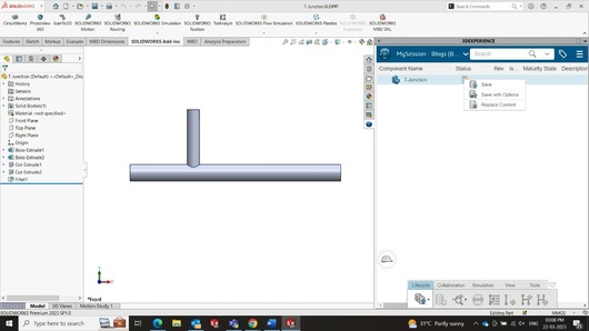
Once, we click on save, the CAD file will be uploaded and saved on Platform in selected
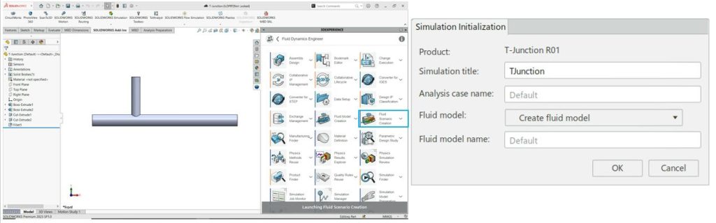
Collaborative space. Once, the CAD files is saved, the user can launch FMK role through
compass and select Fluid Scenario Creation app. This will launch the CFD Solver on Platform
and give a simulation title.
Setup of a simulation study in FMK
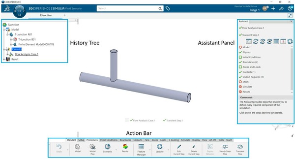
History Tree: Provides the user with all the information that is available and modified during
the analysis.
Action Bar: The action bar is the main command bar, commands that are specific to your
app are organized in sections in this bar.
Assistant Panel: The Assistant is a panel that displays a set of actions that you can perform,
in roughly the order presented, to complete a simulation.
1. Defining Fluid region:
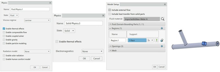
The first step is to define the fluid physics and region along with the fluid material
properties. Since we are using the temperature in the fluids, enable thermal effects and
solid physics. The cube indicates the fluid regions and openings can be used to setup the
boundary conditions. Also, user has to define whether it’s a steady state or transient
analysis.
2. Defining Boundary Conditions:
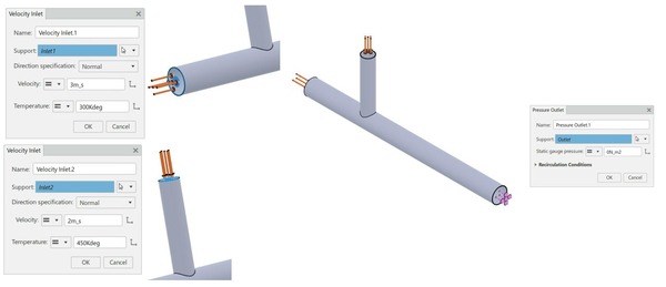
The fluid enters the tube at two different locations with two different velocities and at
different temperatures while exiting through the same outlet.
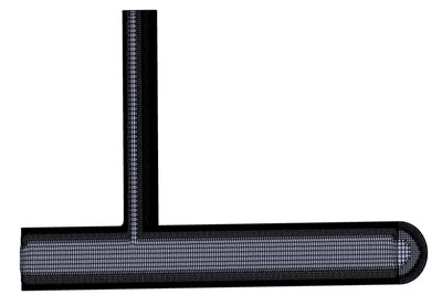
3. Mesh
FMK solver utilizes Body Fitted Mesh.
4. Solve
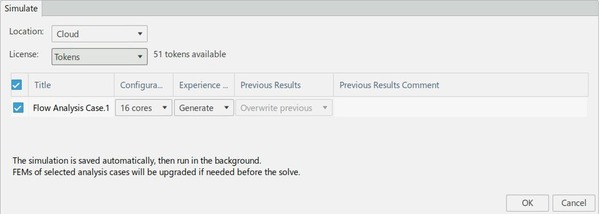
Solver provides the option to execute the simulation in both local i.e., computer and cloud
computation. The solver can utilize cores like 16, 36, 72 and 144. But by default, the user
can make use of upto 16 cores without any additional costs.
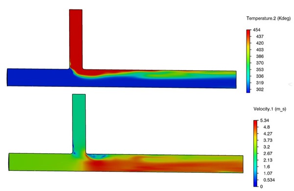
5. Results
Once the analysis is completed, the user can obtain several results like Pressure, Velocity,
Temperature, etc., in the form of contours and XY plots (Graphs).
Try our easy to use simulation tools and improve the product performance.
We Urge You To Call Us For Any Doubts & Clarifications That You May Have. We Are Eager to Talk To You
Call Us: +91 7406663589
 (1 votes, average: 5.00 out of 5)
#365/8, Ground Floor, "Hasmitha Avenue", 16th Main, 4th T Block East, Jayanagar, 4th T Block East, Pattabhirama Nagar, Jayanagar, Bengaluru, Karnataka 560041
Rated 4.7/5 with a total of 62 reviews
"CARAX" Building 4th Floor, 105/1/1/4, Next to Radha Hotel, Pune-Mumbai Xpress Way,Baner,Pune 411045
Rated 4.7/5 with a total of 17 reviews
1002, LODHA Supremus, I-Think Techno Campus,Kanjurmarg EAST - MUMBAI, MH, India – 400042.
Rated 5/5 with a total of 51 reviews
508, Shiti Ratna Complex, Panchwati Cross Road, Ahmedabad-380006
Rated 4.1/5 with a total of 7 reviews
Kanda's Villa, II Floor, AE Block,3362 R, 8th Street, Anna Nagar, Chennai, Tamil Nadu 600040
Rated 4.6/5 with a total of 16 reviews
Flat no F1, first floor, Nakhate corner, Eknath rang mandir road,New Usmanpura, Aurangabad, 431005.
A-101, 1st Floor, The Hub Complex, opp. Shete Hospital, Mahatma Nagar, Parijat Nagar, Nashik, Maharashtra 422005.
Level 7, Octave 3B Salarpuria Sattva Knowledge City, Inorbit Mall Road, Raidurg Village, Hi-tech City, Hyderabad, Telangana - 500081, India

pin up yukle https://azerbaijancuisine.com/# pin up apk yukle
pin-up cazino
mexican rx online mexican pharmacy northern doctors п»їbest mexican online pharmacies
buying prescription drugs in mexico northern doctors pharmacy п»їbest mexican online pharmacies
mexican rx online mexican northern doctors buying from online mexican pharmacy
mexican border pharmacies shipping to usa mexican pharmacy online mexican pharmaceuticals online
https://northern-doctors.org/# medicine in mexico pharmacies
purple pharmacy mexico price list: mexican pharmacy online – reputable mexican pharmacies online
https://northern-doctors.org/# mexican pharmacy
mexican drugstore online: mexican northern doctors – mexican pharmaceuticals online
medication from mexico pharmacy: mexican northern doctors – buying prescription drugs in mexico online
http://northern-doctors.org/# mexico pharmacy
mexican mail order pharmacies: mexican pharmacy – buying prescription drugs in mexico
mexico drug stores pharmacies: mexican pharmacy northern doctors – buying from online mexican pharmacy
https://northern-doctors.org/# medication from mexico pharmacy
buying prescription drugs in mexico: mexican northern doctors – mexican rx online
mexican drugstore online: mexican pharmacy online – medication from mexico pharmacy
http://northern-doctors.org/# mexico pharmacies prescription drugs
pharmacies in mexico that ship to usa mexican northern doctors buying prescription drugs in mexico
mexican pharmacy: mexican northern doctors – mexico drug stores pharmacies
https://northern-doctors.org/# п»їbest mexican online pharmacies
mexican pharmacy: mexican pharmacy – mexico pharmacy
mexican online pharmacies prescription drugs: mexican northern doctors – pharmacies in mexico that ship to usa
http://northern-doctors.org/# mexico pharmacies prescription drugs
medicine in mexico pharmacies: mexican pharmacy online – buying prescription drugs in mexico
best online pharmacies in mexico: mexican pharmacy – medication from mexico pharmacy
https://northern-doctors.org/# buying from online mexican pharmacy
buying from online mexican pharmacy northern doctors pharmacy medicine in mexico pharmacies
mexican border pharmacies shipping to usa: mexican pharmacy online – mexico pharmacy
http://northern-doctors.org/# mexican online pharmacies prescription drugs
mexican pharmacy: Mexico pharmacy that ship to usa – mexican online pharmacies prescription drugs
buying prescription drugs in mexico online: northern doctors – mexican drugstore online
https://northern-doctors.org/# п»їbest mexican online pharmacies
buying prescription drugs in mexico online: mexican pharmacy – best online pharmacies in mexico
http://northern-doctors.org/# mexico drug stores pharmacies
mexico drug stores pharmacies: northern doctors pharmacy – mexican online pharmacies prescription drugs
buying from online mexican pharmacy mexican online pharmacy mexico pharmacies prescription drugs
https://cmqpharma.online/# mexican drugstore online
reputable mexican pharmacies online
mexican drugstore online cmq pharma mexican drugstore online
mexican pharmacy: mexican pharmacy – mexican pharmacy
mexican border pharmacies shipping to usa online mexican pharmacy medication from mexico pharmacy
mexican mail order pharmacies mexican pharmacy online mexico pharmacies prescription drugs
buying prescription drugs in mexico online cmq pharma mexican online pharmacies prescription drugs
pharmacies in mexico that ship to usa
https://cmqpharma.online/# pharmacies in mexico that ship to usa
medication from mexico pharmacy
reputable mexican pharmacies online mexico pharmacy mexican drugstore online
buying prescription drugs in mexico online mexican pharmacy online best online pharmacies in mexico
reputable mexican pharmacies online cmq pharma mexico drug stores pharmacies
canadian king pharmacy legal to buy prescription drugs from canada canadianpharmacyworld com
https://foruspharma.com/# mexico pharmacies prescription drugs
top 10 online pharmacy in india top online pharmacy india best india pharmacy
п»їlegitimate online pharmacies india online shopping pharmacy india mail order pharmacy india
http://foruspharma.com/# mexican rx online
reputable indian pharmacies online pharmacy india top 10 online pharmacy in india
http://canadapharmast.com/# canada pharmacy online legit
order generic clomid without rx: can i get clomid no prescription – can i get generic clomid
amoxicillin online without prescription: amoxicillin canada price – where to buy amoxicillin 500mg
doxycycline mexico: doxycycline generic – cost of doxycycline 40 mg
ciprofloxacin order online: ciprofloxacin generic price – buy cipro online
п»їpaxlovid: paxlovid india – paxlovid buy
where can i get clomid no prescription: where to get generic clomid without dr prescription – cost of generic clomid
cipro 500mg best prices: buy cipro – purchase cipro
where can i buy generic clomid without dr prescription: how to get generic clomid price – generic clomid pills
mexico drug stores pharmacies mexican border pharmacies shipping to usa medicine in mexico pharmacies
https://mexicandeliverypharma.com/# best online pharmacies in mexico
mexican drugstore online: п»їbest mexican online pharmacies – mexican mail order pharmacies
mexico pharmacies prescription drugs: mexican drugstore online – buying prescription drugs in mexico
buying prescription drugs in mexico online best online pharmacies in mexico п»їbest mexican online pharmacies
buying prescription drugs in mexico: mexican drugstore online – buying prescription drugs in mexico
mexican mail order pharmacies: purple pharmacy mexico price list – buying prescription drugs in mexico
https://mexicandeliverypharma.online/# mexican pharmaceuticals online
best online pharmacies in mexico reputable mexican pharmacies online mexican drugstore online
mexican rx online: п»їbest mexican online pharmacies – mexico drug stores pharmacies
buying prescription drugs in mexico online: buying from online mexican pharmacy – mexican drugstore online
http://mexicandeliverypharma.com/# mexico drug stores pharmacies
best online pharmacies in mexico mexico pharmacies prescription drugs buying prescription drugs in mexico
mexican online pharmacies prescription drugs: reputable mexican pharmacies online – medication from mexico pharmacy
mexico drug stores pharmacies: medicine in mexico pharmacies – mexican pharmaceuticals online
mexican mail order pharmacies: buying prescription drugs in mexico – mexican mail order pharmacies
mexican drugstore online mexican drugstore online buying from online mexican pharmacy
medication from mexico pharmacy: п»їbest mexican online pharmacies – mexico drug stores pharmacies
mexico drug stores pharmacies: buying prescription drugs in mexico online – mexican pharmaceuticals online
pharmacies in mexico that ship to usa: mexico drug stores pharmacies – pharmacies in mexico that ship to usa
http://mexicandeliverypharma.com/# reputable mexican pharmacies online
mexican rx online mexico drug stores pharmacies mexico pharmacies prescription drugs
mexican online pharmacies prescription drugs: mexico drug stores pharmacies – reputable mexican pharmacies online
pharmacies in mexico that ship to usa: mexican rx online – best online pharmacies in mexico
п»їbest mexican online pharmacies: reputable mexican pharmacies online – mexican mail order pharmacies
medication from mexico pharmacy medication from mexico pharmacy buying prescription drugs in mexico online
mexico drug stores pharmacies: mexican drugstore online – mexican pharmaceuticals online
mexico drug stores pharmacies: purple pharmacy mexico price list – mexico pharmacies prescription drugs
reputable mexican pharmacies online: mexican drugstore online – purple pharmacy mexico price list
buying prescription drugs in mexico online buying prescription drugs in mexico online best online pharmacies in mexico
mexican mail order pharmacies: mexico pharmacies prescription drugs – mexican pharmaceuticals online
medicine in mexico pharmacies: medicine in mexico pharmacies – reputable mexican pharmacies online
best online pharmacies in mexico: medication from mexico pharmacy – purple pharmacy mexico price list
mexico pharmacies prescription drugs mexico pharmacies prescription drugs mexican pharmaceuticals online
reputable mexican pharmacies online: pharmacies in mexico that ship to usa – medicine in mexico pharmacies
purple pharmacy mexico price list: mexican online pharmacies prescription drugs – pharmacies in mexico that ship to usa
mexico drug stores pharmacies: mexican rx online – best online pharmacies in mexico
mexican mail order pharmacies purple pharmacy mexico price list mexican mail order pharmacies
mexican online pharmacies prescription drugs: buying from online mexican pharmacy – mexican pharmaceuticals online
п»їbest mexican online pharmacies: mexican mail order pharmacies – buying prescription drugs in mexico online
buying prescription drugs in mexico online: mexico drug stores pharmacies – buying from online mexican pharmacy
mexico pharmacy mexican border pharmacies shipping to usa mexican drugstore online
mexico drug stores pharmacies: п»їbest mexican online pharmacies – п»їbest mexican online pharmacies
mexican rx online: mexican drugstore online – reputable mexican pharmacies online
medication from mexico pharmacy: mexico pharmacies prescription drugs – medicine in mexico pharmacies
reputable mexican pharmacies online mexican mail order pharmacies mexican pharmaceuticals online
п»їbest mexican online pharmacies: п»їbest mexican online pharmacies – mexican drugstore online
pharmacies in mexico that ship to usa: mexican rx online – mexico drug stores pharmacies
mexican drugstore online: mexican border pharmacies shipping to usa – mexican border pharmacies shipping to usa
mexican pharmacy mexican drugstore online mexican pharmacy
mexican pharmaceuticals online: buying prescription drugs in mexico online – pharmacies in mexico that ship to usa
medication from mexico pharmacy: mexican rx online – mexican drugstore online
medicine in mexico pharmacies: mexican rx online – mexican pharmaceuticals online
medication from mexico pharmacy mexico pharmacies prescription drugs medicine in mexico pharmacies
п»їbest mexican online pharmacies: п»їbest mexican online pharmacies – buying prescription drugs in mexico
mexico drug stores pharmacies: mexico drug stores pharmacies – pharmacies in mexico that ship to usa
mexico pharmacies prescription drugs: buying prescription drugs in mexico online – mexican drugstore online
best online pharmacies in mexico reputable mexican pharmacies online best online pharmacies in mexico
п»їbest mexican online pharmacies: purple pharmacy mexico price list – medicine in mexico pharmacies
mexican rx online: mexico pharmacies prescription drugs – mexican mail order pharmacies
mexican border pharmacies shipping to usa: mexico drug stores pharmacies – buying prescription drugs in mexico
mexico drug stores pharmacies purple pharmacy mexico price list mexican online pharmacies prescription drugs
reputable mexican pharmacies online: best online pharmacies in mexico – mexican rx online
mexican mail order pharmacies: best online pharmacies in mexico – mexico drug stores pharmacies
medication from mexico pharmacy: buying prescription drugs in mexico – mexican border pharmacies shipping to usa
mexican pharmacy mexican drugstore online mexican online pharmacies prescription drugs
buying prescription drugs in mexico online: mexican mail order pharmacies – buying prescription drugs in mexico
buying prescription drugs in mexico online: medicine in mexico pharmacies – buying from online mexican pharmacy
mexico drug stores pharmacies: purple pharmacy mexico price list – buying prescription drugs in mexico
best online pharmacies in mexico mexico pharmacy mexican online pharmacies prescription drugs
buying prescription drugs in mexico: medicine in mexico pharmacies – purple pharmacy mexico price list
mexico pharmacies prescription drugs: mexico drug stores pharmacies – buying prescription drugs in mexico
mexico drug stores pharmacies: pharmacies in mexico that ship to usa – mexico drug stores pharmacies
medication from mexico pharmacy mexico drug stores pharmacies mexican rx online
prednisone 5mg capsules 6 prednisone prednisone pills cost
prednisone 25mg from canada: prednisone 5 50mg tablet price – generic prednisone otc
http://nolvadexbestprice.pro/# tamoxifen citrate pct
https://cytotecbestprice.pro/# cytotec pills buy online
cytotec buy online usa purchase cytotec п»їcytotec pills online
tamoxifen endometrium: tamoxifen citrate pct – tamoxifen premenopausal
https://propeciabestprice.pro/# get propecia pills
https://propeciabestprice.pro/# cost of cheap propecia prices
zithromax order online uk zithromax 500 mg lowest price online zithromax pill
nolvadex price: aromatase inhibitor tamoxifen – tamoxifen citrate pct
https://nolvadexbestprice.pro/# femara vs tamoxifen
http://prednisonebestprice.pro/# prednisone 50mg cost
cytotec abortion pill п»їcytotec pills online buy cytotec over the counter
order cheap propecia without dr prescription: cheap propecia for sale – cost generic propecia without dr prescription
buying generic propecia no prescription: cost of generic propecia without insurance – propecia cost
natural alternatives to tamoxifen: how to lose weight on tamoxifen – tamoxifen and antidepressants
https://prednisonebestprice.pro/# prednisone without prescription medication
zithromax tablets for sale: zithromax z-pak price without insurance – zithromax for sale us
how to purchase prednisone online: 10mg prednisone daily – prednisone 10 mg daily
п»їcytotec pills online: Abortion pills online – cytotec buy online usa
https://nolvadexbestprice.pro/# tamoxifen generic
where can i get zithromax over the counter: zithromax 500 tablet – zithromax generic price
prednisone in india: prednisone cost us – buy 40 mg prednisone
viagra generico sandoz: viagra prezzo – pillole per erezioni fortissime
Farmacia online piГ№ conveniente: Farmacie che vendono Cialis senza ricetta – Farmacie online sicure
migliori farmacie online 2024: Avanafil 50 mg – п»їFarmacia online migliore
https://kamagrait.pro/# farmacie online sicure
farmacia online piГ№ conveniente: farmacia online migliore – top farmacia online
top farmacia online: kamagra gold – farmacie online affidabili
farmacia online senza ricetta: Farmacie che vendono Cialis senza ricetta – farmaci senza ricetta elenco
farmacia online: avanafil generico – farmacie online affidabili
https://cialisgenerico.life/# п»їFarmacia online migliore
farmacie online autorizzate elenco: Avanafil a cosa serve – farmacie online sicure
Farmacia online miglior prezzo: Cialis generico recensioni – top farmacia online
http://viagragenerico.site/# pillole per erezione immediata
viagra professional: buy sildenafil online usa – free viagra
https://tadalafil.auction/# online cialis australia
buy viagra professional: Buy Viagra online cheap – over the counter alternative to viagra
free samples for cialis: Generic Tadalafil 20mg price – buying cialis internet
https://sildenafil.llc/# buy viagra online without a prescription
viagra professional: buy sildenafil online canada – viagra price
http://indiapharmacy.shop/# top 10 online pharmacy in india
ed medications online
buy ed pills: ed pills online – ed pills for sale
http://indiapharmacy.shop/# india pharmacy mail order
http://indiapharmacy.shop/# world pharmacy india
online erectile dysfunction pills
mexico drug stores pharmacies: Best pharmacy in Mexico – medication from mexico pharmacy
https://mexicopharmacy.win/# reputable mexican pharmacies online
ed pills for sale
https://indiapharmacy.shop/# india online pharmacy
online ed meds: online ed prescription same-day – ed pills cheap
cheapest online pharmacy india: Online medicine home delivery – cheapest online pharmacy india
https://edpillpharmacy.store/# buy ed pills online
Online medicine order: Indian pharmacy international shipping – indianpharmacy com
buy ed pills: Best ED meds online – ed medicines online
https://indiapharmacy.shop/# п»їlegitimate online pharmacies india
indianpharmacy com: Online medicine home delivery – indianpharmacy com
top online pharmacy india: Top mail order pharmacies – reputable indian pharmacies
https://edpillpharmacy.store/# erection pills online
cheapest ed pills: cheap ed pills online – online erectile dysfunction medication
https://indiapharmacy.shop/# indianpharmacy com
online erectile dysfunction: online ed prescription same-day – buy ed medication online
mexico pharmacies prescription drugs: Best pharmacy in Mexico – medicine in mexico pharmacies
http://edpillpharmacy.store/# best ed pills online
mexican border pharmacies shipping to usa: best online pharmacies in mexico – pharmacies in mexico that ship to usa
http://indiapharmacy.shop/# india pharmacy
medication from mexico pharmacy: mexico pharmacy win – mexico drug stores pharmacies
medicine in mexico pharmacies: Certified Mexican pharmacy – mexican rx online
http://indiapharmacy.shop/# top 10 online pharmacy in india
mexico drug stores pharmacies: Purple pharmacy online ordering – mexico drug stores pharmacies
ed doctor online: Cheap ED pills online – best ed meds online
reputable indian pharmacies: Top online pharmacy in India – indian pharmacy online
india pharmacy mail order: indian pharmacy – best india pharmacy
medication from mexico pharmacy: mexican pharmacy – mexican border pharmacies shipping to usa
lipitor 20mg price: Atorvastatin 20 mg buy online – lipitor cost in canada
is nolvadex legal nolvadex for sale does tamoxifen cause joint pain
Cytotec 200mcg price http://furosemide.win/# lasix generic
lasix 100 mg
https://lisinopril.guru/# rx drug lisinopril
tamoxifen 20 mg tablet: tamoxifen therapy – nolvadex estrogen blocker
lasix 20 mg buy furosemide lasix 100mg
cytotec abortion pill https://lipitor.guru/# lipitor purchase
lasix for sale
lisinopril prescription: Lisinopril online prescription – buying lisinopril online
https://lipitor.guru/# buy lipitor from india
order cytotec online https://tamoxifen.bid/# tamoxifen therapy
lasix dosage
lisinopril for sale online Buy Lisinopril 20 mg online lisinopril 10 mg brand name in india
http://furosemide.win/# lasix side effects
buy cytotec online fast delivery https://lipitor.guru/# liptor
lasix 100 mg
https://lipitor.guru/# lipitor 40 mg price australia
lasix for sale: buy furosemide – lasix 40 mg
does tamoxifen cause joint pain: buy tamoxifen citrate – tamoxifen postmenopausal
https://cytotec.pro/# buy cytotec
buy cytotec online fast delivery: buy misoprostol tablet – order cytotec online
Abortion pills online http://furosemide.win/# lasix 40 mg
lasix tablet
generic cost of lipitor: Lipitor 10 mg price – lipitor 20 mg generic
https://furosemide.win/# lasix medication
buy lipitor online uk: buy atorvastatin online – lipitor coupon
buy misoprostol over the counter https://lisinopril.guru/# lisinopril 5mg tab
lasix
furosemida 40 mg: furosemide online – lasix side effects
lasix generic: cheap lasix – furosemida
buy cytotec in usa https://lipitor.guru/# lipitor generic brand
buy lasix online
lipitor prescription prices: cheapest ace inhibitor – lipitor price in canada
cytotec online: buy cytotec over the counter – п»їcytotec pills online
cytotec online http://cytotec.pro/# buy cytotec pills
lasix 100 mg
buy cytotec over the counter: buy misoprostol tablet – cytotec buy online usa
https://mexstarpharma.online/# mexican drugstore online
reputable mexican pharmacies online best online pharmacies in mexico mexican online pharmacies prescription drugs
http://easyrxcanada.com/# canadian pharmacy meds review
https://easyrxcanada.com/# canadian pharmacy phone number
reputable indian online pharmacy top online pharmacy india pharmacy website india
mexican border pharmacies shipping to usa: mexican border pharmacies shipping to usa – mexican rx online
india online pharmacy: online pharmacy india – indian pharmacy paypal
http://easyrxcanada.com/# canadian mail order pharmacy
https://easyrxcanada.com/# legitimate canadian pharmacies
mexican mail order pharmacies: mexican border pharmacies shipping to usa – mexican mail order pharmacies
mexican online pharmacies prescription drugs: mexican online pharmacies prescription drugs – mexican mail order pharmacies
http://easyrxindia.com/# india pharmacy mail order
https://easyrxindia.shop/# indian pharmacy online
reputable indian pharmacies: п»їlegitimate online pharmacies india – best india pharmacy
canadian pharmacy tampa: canada drugs online review – cheapest pharmacy canada
https://easyrxindia.shop/# top 10 online pharmacy in india
guvenilir slot siteleri: slot siteleri 2024 – guvenilir slot siteleri
yeni slot siteleri: en guvenilir slot siteleri – en iyi slot siteleri
http://sweetbonanza.network/# sweet bonanza kazanc
en guvenilir slot siteleri: deneme veren slot siteleri – slot casino siteleri
https://slotsiteleri.bid/# slot kumar siteleri
deneme bonusu veren siteler: slot casino siteleri – guvenilir slot siteleri 2024
slot kumar siteleri: oyun siteleri slot – deneme bonusu veren siteler
http://slotsiteleri.bid/# en guvenilir slot siteleri
guvenilir slot siteleri: en iyi slot siteleri – bonus veren slot siteleri
https://sweetbonanza.network/# sweet bonanza yasal site
slot siteleri guvenilir: en iyi slot siteler – deneme bonusu veren slot siteleri
https://denemebonusuverensiteler.win/# deneme bonusu veren siteler
vavada casino: vavada online casino – вавада
Hello very nice blog!! Man .. Beautiful .. Superb .. I will bookmark your blog and take the feeds also…I’m satisfied to find numerous useful info here within the post, we want develop extra strategies on this regard, thanks for sharing. . . . . .
https://1win.directory/# 1вин официальный сайт
pin up казино: пин ап вход – пин ап зеркало
зеркало 1хбет: 1xbet – 1хбет официальный сайт
http://vavada.auction/# вавада рабочее зеркало
пин ап казино вход: пинап казино – пин ап зеркало
http://1xbet.contact/# 1xbet зеркало рабочее на сегодня
пинап казино: pin up casino – пин ап
1xbet официальный сайт: 1xbet скачать – 1xbet официальный сайт
https://1xbet.contact/# 1xbet зеркало
1win вход: 1win официальный сайт – 1вин сайт
https://pharm24on.com/# inhouse pharmacy depo provera
amoxicillin price pharmacy
amoxicillin online pharmacy no prescription: best pharmacy store – men’s health pharmacy viagra
https://onlineph24.com/# mexico online pharmacy
cialis pharmacy rx one
pharmacy without dr prescriptions: morrisons pharmacy viagra – nabp pharmacy viagra
https://onlineph24.com/# pharmacy stuff store
online pharmacy pain medication
united pharmacy naltrexone: doxycycline pharmacy price – Aebgmearp
rx express pharmacy hurley ms: buy provigil online pharmacy – qatar pharmacy cialis
best online cialis pharmacy: meijer pharmacy lipitor – rx pharmacy india
Myambutol: viagra from indian pharmacy – online pharmacy legit
levitra online pharmacy no prescription: ez pharmacy – pharmacy clothes store
viagra at guardian pharmacy: phuket pharmacy viagra – united pharmacy propecia
clomiphene pharmacy: what pharmacy sells azithromycin – people pharmacy zocor
world pharmacy india best india pharmacy india online pharmacy
online pharmacy adderall: viagra in hong kong pharmacy – vons pharmacy
https://mexicopharmacy.cheap/# mexico pharmacies prescription drugs
medication from mexico pharmacy: mexico drug stores pharmacies – buying from online mexican pharmacy
india pharmacy: Online medicine home delivery – best india pharmacy
mexican pharmaceuticals online: mexican border pharmacies shipping to usa – mexican border pharmacies shipping to usa
buying from online mexican pharmacy mexico drug stores pharmacies mexico drug stores pharmacies
https://pharmbig24.com/# avodart pharmacy
indian pharmacy online: top 10 pharmacies in india – top 10 online pharmacy in india
reputable indian pharmacies: world pharmacy india – Online medicine home delivery
top 10 pharmacies in india Online medicine home delivery indian pharmacy
https://pharmbig24.com/# rx pharmacy viagra
mexico drug stores pharmacies: mexican pharmaceuticals online – purple pharmacy mexico price list
prescriptions online pharmacy clindamycin target pharmacy tricare pharmacy online
pharmacy reviewer provigil: online cialis uk pharmacy – adipex online us pharmacy
best india pharmacy: india pharmacy mail order – online shopping pharmacy india
mexico drug stores pharmacies buying prescription drugs in mexico online mexico pharmacies prescription drugs
http://indianpharmacy.company/# Online medicine order
mexico drug stores pharmacies: mexican rx online – mexican mail order pharmacies
arimidex online pharmacy: rx pharmacy near me – us pharmacy viagra online
india pharmacy mail order mail order pharmacy india buy prescription drugs from india
https://mexicopharmacy.cheap/# medicine in mexico pharmacies
п»їbest mexican online pharmacies: mexican rx online – best online pharmacies in mexico
buying prescription drugs in mexico online: medicine in mexico pharmacies – medication from mexico pharmacy
mexican pharmaceuticals online mexico pharmacies prescription drugs mexican mail order pharmacies
A large percentage of of what you say is astonishingly precise and that makes me wonder the reason why I had not looked at this in this light before. Your article truly did turn the light on for me as far as this specific issue goes. Nonetheless at this time there is 1 position I am not necessarily too cozy with and whilst I attempt to reconcile that with the actual core theme of the point, let me observe what the rest of your subscribers have to point out.Nicely done.
zithromax prices pharmacy: kaiser permanente online pharmacy – latisse online pharmacy
https://pharmbig24.online/# viagra certified pharmacy online
mexico drug stores pharmacies: medication from mexico pharmacy – reputable mexican pharmacies online
mexico drug stores pharmacies mexican drugstore online mexico drug stores pharmacies
online isotretinoin pharmacy: sav on pharmacy store locator – legitimate mexican pharmacy online
buying prescription drugs in mexico mexican pharmaceuticals online buying prescription drugs in mexico online
mexico drug stores pharmacies: mexican border pharmacies shipping to usa – mexico drug stores pharmacies
https://pharmbig24.online/# buy latisse online pharmacy
indianpharmacy com: best india pharmacy – mail order pharmacy india
mexico drug stores pharmacies п»їbest mexican online pharmacies buying from online mexican pharmacy
best online propecia pharmacy: online pharmacy reviews cialis – shoppers drug mart pharmacy
reputable mexican pharmacies online: buying prescription drugs in mexico – mexican mail order pharmacies
https://indianpharmacy.company/# indian pharmacy
cheapest online pharmacy india top 10 pharmacies in india india pharmacy
target pharmacy: Feldene – tadalafil india pharmacy
pharmacies in mexico that ship to usa: mexican border pharmacies shipping to usa – mexican pharmaceuticals online
mexico pharmacies prescription drugs medication from mexico pharmacy reputable mexican pharmacies online
casibom guncel giris adresi casibom 158 giris casibom giris
starzbet guvenilir mi starzbet giris starzbet guncel giris
http://starzbet.shop/# starzbet guncel giris
http://betine.online/# betine guncel
betine promosyon kodu 2024 betine com guncel giris betine guncel giris
http://betine.online/# betine
starzbet guvenilir mi starzbet giris starzbet guncel giris
https://casibom.auction/# casibom 158 giris
farmacia online envГo gratis: Cialis sin receta – farmacias online seguras en espaГ±a
viagra para hombre precio farmacias comprar viagra farmacia gibraltar online viagra
п»їfarmacia online espaГ±a: comprar cialis online seguro opiniones – farmacias online seguras
https://farmaciaeu.com/# farmacias online seguras
farmacia online barata: farmacia 24 horas – farmacia online barata
farmacias online seguras Tadalafilo precio п»їfarmacia online espaГ±a
https://tadalafilo.bid/# farmacias online seguras en espaГ±a
viagra online cerca de zaragoza: Viagra sildenafilo – comprar viagra online en andorra
http://farmaciaeu.com/# п»їfarmacia online espaГ±a
se puede comprar sildenafil sin receta: viagra precio – se puede comprar viagra sin receta
https://farmaciaeu.com/# farmacia online espaГ±a envГo internacional
farmacias online seguras
farmacias direct: farmacia online 24 horas – farmacias online baratas
https://sildenafilo.men/# п»їViagra online cerca de Madrid
farmacia online barcelona: farmacia online barata y fiable – farmacia online 24 horas
https://farmaciaeu.com/# farmacia online 24 horas
farmacias online seguras
farmacia online madrid: comprar cialis online sin receta – farmacia en casa online descuento
https://tadalafilo.bid/# farmacia online envГo gratis
farmacia online 24 horas: comprar cialis original – farmacia online barcelona
Farmacie online sicure: Cialis generico recensioni – acquistare farmaci senza ricetta
farmacia online Cialis generico recensioni farmacia online senza ricetta
Farmacie online sicure Cialis generico recensioni Farmacie online sicure
http://sildenafilit.pro/# dove acquistare viagra in modo sicuro
acquisto farmaci con ricetta
acquistare farmaci senza ricetta: Cialis generico 20 mg 8 compresse prezzo – acquistare farmaci senza ricetta
comprare farmaci online con ricetta: Cialis generico recensioni – top farmacia online
farmacia online piГ№ conveniente Cialis generico controindicazioni farmacie online affidabili
п»їFarmacia online migliore Farmacia online migliore Farmacia online piГ№ conveniente
cialis farmacia senza ricetta: viagra farmacia – viagra generico prezzo piГ№ basso
comprare farmaci online con ricetta: Farmacie on line spedizione gratuita – farmaci senza ricetta elenco
http://tadalafilit.com/# farmacia online
acquistare farmaci senza ricetta
п»їFarmacia online migliore: Cialis generico prezzo – migliori farmacie online 2024
farmacie online autorizzate elenco acquistare farmaci senza ricetta Farmacia online miglior prezzo
viagra generico sandoz viagra kamagra senza ricetta in farmacia
top farmacia online: Cialis generico prezzo – acquisto farmaci con ricetta
viagra generico prezzo piГ№ basso: acquisto viagra – viagra prezzo farmacia 2023
https://farmaciait.men/# acquistare farmaci senza ricetta
Farmacia online miglior prezzo
comprare farmaci online con ricetta Farmacie online sicure Farmacia online miglior prezzo
п»їFarmacia online migliore: Brufen 600 senza ricetta – farmacia online senza ricetta
farmacia online senza ricetta farmacia online top farmacia online
cialis farmacia senza ricetta: viagra online siti sicuri – viagra ordine telefonico
viagra generico prezzo piГ№ basso viagra senza ricetta pillole per erezione in farmacia senza ricetta
http://farmaciait.men/# farmacia online
п»їFarmacia online migliore
comprare farmaci online all’estero Cialis generico prezzo farmacie online autorizzate elenco
top farmacia online: Cialis generico prezzo – farmacie online affidabili
Farmacia online piГ№ conveniente comprare farmaci online con ricetta farmacia online piГ№ conveniente
Farmacie online sicure Farmacie che vendono Cialis senza ricetta п»їFarmacia online migliore
viagra pfizer 25mg prezzo: viagra prezzo – gel per erezione in farmacia
http://brufen.pro/# Brufen 600 prezzo
farmaci senza ricetta elenco
farmacia online senza ricetta: farmacia online migliore – migliori farmacie online 2024
Farmacie on line spedizione gratuita Farmacie on line spedizione gratuita farmacie online affidabili
viagra online in 2 giorni acquisto viagra viagra generico in farmacia costo
farmacia online: Farmacie on line spedizione gratuita – migliori farmacie online 2024
https://sildenafilit.pro/# pillole per erezione immediata
top farmacia online
farmacie online affidabili: Farmacie on line spedizione gratuita – top farmacia online
comprare farmaci online all’estero Farmacie che vendono Cialis senza ricetta Farmacie on line spedizione gratuita
acquistare farmaci senza ricetta Farmacie on line spedizione gratuita Farmacie on line spedizione gratuita
farmacia online senza ricetta: Cialis generico controindicazioni – farmacia online
http://farmaciait.men/# Farmacie on line spedizione gratuita
top farmacia online
Farmacia online piГ№ conveniente Farmacia online piu conveniente farmacia online senza ricetta
lasix side effects: lasix furosemide – lasix uses
Buy compounded semaglutide online: buy semaglutide online – Buy compounded semaglutide online
Buy compounded semaglutide online: Semaglutide pharmacy price – rybelsus
mail order prednisone online prednisone mail order prednisone
https://ventolininhaler.pro/# ventolin tablet 4mg
buy furosemide online: buy furosemide – lasix furosemide 40 mg
ventolin hfa price: buy albuterol inhaler – ventolin otc uk
neurontin 600 mg pill 32 neurontin buy generic neurontin
Rybelsus 7mg: Buy semaglutide pills – Semaglutide pharmacy price
https://prednisolone.pro/# buy prednisone online from canada
rybelsus: rybelsus price – rybelsus cost
lasix dosage: cheap lasix – lasix medication
prednisone prices: prednisone prices – buy prednisone online usa
http://gabapentin.site/# neurontin cap 300mg
purchase neurontin: medicine neurontin – neurontin india
90 mcg ventolin: Ventolin inhaler best price – can i buy ventolin online
neurontin 100mg tab: buy neurontin canada – neurontin rx
rybelsus: buy semaglutide online – rybelsus
https://canadapharma.shop/# canadian pharmacy price checker
medication from mexico pharmacy: medication from mexico – best online pharmacies in mexico
canadian medications: canadian pharmacy 365 – safe online pharmacies in canada
medicine in mexico pharmacies mexican pharmacy buying prescription drugs in mexico
http://indiadrugs.pro/# reputable indian online pharmacy
onlinepharmaciescanada com: Pharmacies in Canada that ship to the US – canadianpharmacymeds
pharmacies in mexico that ship to usa: medication from mexico pharmacy – mexican online pharmacies prescription drugs
http://indiadrugs.pro/# online shopping pharmacy india
canadianpharmacyworld Pharmacies in Canada that ship to the US reputable canadian pharmacy
mexican online pharmacies prescription drugs: medicine in mexico pharmacies – purple pharmacy mexico price list
https://indiadrugs.pro/# reputable indian pharmacies
mexico drug stores pharmacies: mexican pharmacy – medicine in mexico pharmacies
buying prescription drugs in mexico online https://mexicanpharma.icu/# mexican border pharmacies shipping to usa
mexico pharmacies prescription drugs
ed drugs online from canada Cheapest online pharmacy best canadian online pharmacy
http://mexicanpharma.icu/# mexican mail order pharmacies
https://canadapharma.shop/# canadian mail order pharmacy
my canadian pharmacy Online medication home delivery best rated canadian pharmacy
http://canadapharma.shop/# canadian pharmacy antibiotics
vente de mГ©dicament en ligne pharmacie en ligne livraison europe pharmacie en ligne fiable
Prix du Viagra en pharmacie en France: Viagra sans ordonnance 24h – Prix du Viagra 100mg en France
http://pharmaciepascher.pro/# acheter mГ©dicament en ligne sans ordonnance
mexican online pharmacies prescription drugs: pharmacies in mexico that ship to usa – mexico pharmacies prescription drugs
purple pharmacy mexico price list
pharmacie en ligne livraison europe: Cialis sans ordonnance pas cher – pharmacie en ligne france livraison belgique
https://clssansordonnance.icu/# pharmacie en ligne sans ordonnance
pharmacie en ligne france fiable: Medicaments en ligne livres en 24h – п»їpharmacie en ligne france
Thank you, I have recently been looking for information about this topic for ages and yours is the best I have discovered till now. But, what about the conclusion? Are you sure about the source?
pharmacie en ligne avec ordonnance: Cialis sans ordonnance 24h – trouver un mГ©dicament en pharmacie
SildГ©nafil 100 mg prix en pharmacie en France viagra sans ordonnance Viagra sans ordonnance 24h Amazon
Pharmacie Internationale en ligne: Cialis generique prix – Pharmacie en ligne livraison Europe
pharmacie en ligne france livraison belgique: Acheter Cialis – trouver un mГ©dicament en pharmacie
http://vgrsansordonnance.com/# Viagra homme prix en pharmacie sans ordonnance
pharmacie en ligne france livraison belgique Cialis generique achat en ligne Pharmacie en ligne livraison Europe
Viagra homme prix en pharmacie sans ordonnance: Viagra pas cher paris – Prix du Viagra en pharmacie en France
Regards for this post, I am a big fan of this website would like to continue updated.
pharmacie en ligne pas cher: Pharmacies en ligne certifiees – п»їpharmacie en ligne france
My developer is trying to convince me to move to .net from PHP. I have always disliked the idea because of the costs. But he’s tryiong none the less. I’ve been using WordPress on numerous websites for about a year and am concerned about switching to another platform. I have heard good things about blogengine.net. Is there a way I can import all my wordpress posts into it? Any help would be really appreciated!
semaglutide cost: buy rybelsus online – semaglutide tablets
https://ozempic.art/# buy cheap ozempic
buy semaglutide pills semaglutide tablets semaglutide cost
http://rybelsus.shop/# buy semaglutide pills
Ozempic without insurance: ozempic coupon – ozempic
http://ozempic.art/# buy cheap ozempic
rybelsus pill rybelsus cost semaglutide online
buy ozempic pills online: ozempic coupon – buy ozempic
rybelsus pill: rybelsus coupon – buy rybelsus online
https://ozempic.art/# Ozempic without insurance
rybelsus pill: semaglutide cost – semaglutide cost
http://ozempic.art/# buy cheap ozempic
rybelsus price buy semaglutide pills semaglutide cost
Ozempic without insurance: ozempic cost – Ozempic without insurance
ozempic: buy ozempic – ozempic
http://ozempic.art/# ozempic generic
https://rybelsus.shop/# semaglutide online
ozempic cost ozempic coupon buy ozempic pills online
buy cheap ozempic: buy cheap ozempic – ozempic coupon
semaglutide tablets: rybelsus price – buy semaglutide online
buy ozempic: ozempic generic – buy ozempic pills online
https://rybelsus.shop/# rybelsus pill
ozempic cost: buy ozempic – ozempic generic
rybelsus price buy rybelsus online rybelsus price
buy semaglutide online: rybelsus coupon – cheapest rybelsus pills
ozempic generic: ozempic online – ozempic cost
buy ozempic ozempic online buy cheap ozempic
ozempic cost: ozempic online – buy ozempic
cheapest rybelsus pills: rybelsus cost – rybelsus cost
http://rybelsus.shop/# semaglutide cost
http://ozempic.art/# buy ozempic pills online
ozempic coupon: buy ozempic – buy ozempic
http://rybelsus.shop/# rybelsus cost
semaglutide cost: cheapest rybelsus pills – cheapest rybelsus pills
https://rybelsus.shop/# buy semaglutide pills
https://ozempic.art/# buy ozempic
ozempic coupon ozempic generic buy ozempic pills online
https://ozempic.art/# ozempic online
buy rybelsus online semaglutide online rybelsus cost
http://rybelsus.shop/# rybelsus coupon
ozempic cost: buy ozempic pills online – ozempic cost
https://ozempic.art/# buy ozempic pills online
buy ozempic buy ozempic pills online ozempic online
pinup az: pinup az – pin up azerbaijan
pin up casino pin up guncel giris pin-up bonanza
pin up casino: pin up casino – pin up bet
pin up казино: pin up – pin up
pin up казино пин ап казино вход pin up
pin up casino: pin up casino giris – pin-up casino
пин ап казино вход http://pinupaz.bid/# pin up azerbaijan
пин ап казахстан
пинап казино: пинап кз – пин ап казино
pin up aviator: pin up bet – pin up aviator
пинап кз пинап казино пинап казино
пинап казино http://pinupaz.bid/# pin up az
pin up kz
pin-up casino giris: pin up aviator – pin up giris
пинап кз: pin up казино – пин ап
https://pinupturkey.pro/# pin up casino giris
pin up казино пин ап пинап казино
http://pinupturkey.pro/# pin-up casino giris
pin up casino: pin-up bonanza – pin-up bonanza
pin-up casino giris pin up casino pinup az
пин ап кз http://pinupkz.tech/# pin up kz
пинап кз
https://pinupturkey.pro/# pin up guncel giris
pin-up kazino: pin-up kazino – pin up azerbaijan
пин ап казино пин ап официальный сайт пин ап официальный сайт
pin up казино https://pinupkz.tech/# пин ап
пин ап кз
pin up casino guncel giris: pin-up bonanza – pin-up casino giris
https://pinupaz.bid/# pinup az
pin up 306 pinup azerbaycan pin-up oyunu
buy amoxicillin from canada: where to get amoxicillin over the counter – amoxicillin 500 mg for sale
cheap Rybelsus 14 mg rybelsus price Rybelsus 7mg
https://stromectol.agency/# minocycline 50 mg
https://stromectol.agency/# ivermectin cost
http://stromectol.agency/# minocycline 50mg pills
cost of amoxicillin 30 capsules: amoxicillin 500 capsule – amoxicillin 800 mg price
neurontin gel gabapentin price neurontin mexico
https://semaglutide.win/# rybelsus
buy ivermectin cream for humans: order stromectol – stromectol xr
ivermectin cost canada buy stromectol online ivermectin where to buy for humans
https://stromectol.agency/# minocycline pac
zithromax 250 price
http://zithromax.company/# where can i purchase zithromax online
https://zithromax.company/# can you buy zithromax over the counter
buy gabapentin online gabapentin price can you buy neurontin over the counter
zithromax 500mg over the counter: generic zithromax – zithromax capsules price
https://stromectol.agency/# stromectol in canada
http://zithromax.company/# zithromax cost canada
zithromax antibiotic
http://semaglutide.win/# order Rybelsus for weight loss
https://zithromax.company/# zithromax antibiotic
neurontin gel order gabapentin gabapentin medication
minocycline capsule: stromectol for sale – minocycline 100mg for acne
https://gabapentin.auction/# neurontin cost australia
generic zithromax medicine
minocycline 100mg tablets cheapest stromectol what is minocycline 50 mg used for
Rybelsus 14 mg price: semaglutide – buy semaglutide online
http://stromectol.agency/# ivermectin 1%
where to get zithromax
I like your writing style truly enjoying this internet site.
https://gabapentin.auction/# neurontin 300 mg caps
neurontin cost generic gabapentin price neurontin 100 mg cost
https://zithromax.company/# buy zithromax without presc
how to get zithromax over the counter
amoxicillin online canada: amoxil best price – buy amoxicillin online uk
http://semaglutide.win/# semaglutide
This is the best weblog for anybody who desires to find out about this topic. You understand a lot its virtually onerous to argue with you (not that I really would need…HaHa). You definitely put a brand new spin on a subject thats been written about for years. Great stuff, just nice!
http://zithromax.company/# zithromax cost
neurontin cap 300mg buy gabapentin neurontin for sale online
https://semaglutide.win/# buy rybelsus
https://amoxil.llc/# amoxicillin 500
zithromax capsules australia
ivermectin 1% cream generic: order stromectol – minocycline acne
https://amoxil.llc/# amoxicillin 500
minocycline 50mg without doctor stromectol price purchase ivermectin
order zithromax over the counter: zithromax 500mg price in india – where can you buy zithromax
http://amoxil.llc/# how to buy amoxicillin online
where can i get zithromax over the counter
where to get amoxicillin over the counter buy amoxil amoxicillin 825 mg
https://gabapentin.auction/# neurontin generic cost
zithromax for sale cheap
price of neurontin: gabapentin price – cost of neurontin 600mg
https://gabapentin.auction/# buy neurontin online
buy semaglutide online Buy semaglutide pills Rybelsus 7mg
https://semaglutide.win/# Rybelsus 14 mg
buy zithromax online fast shipping
rybelsus cost: rybelsus cost – order Rybelsus for weight loss
http://semaglutide.win/# rybelsus
zithromax 500mg price in india zithromax best price zithromax tablets
http://stromectol.agency/# minocycline 100mg without doctor
http://zithromax.company/# zithromax prescription online
zithromax 500mg over the counter
stromectol 0.5 mg: stromectol pill price – stromectol xr
best india pharmacy top online pharmacy india mail order pharmacy india
online pharmacy india: Online medicine order – buy prescription drugs from india
viagra without a doctor prescription http://mexicanpharm24.pro/# reputable mexican pharmacies online
mexican rx online: buying from online mexican pharmacy – reputable mexican pharmacies online
cheap pills online amoxicillin without a doctor’s prescription herbal ed
I think other site proprietors should take this website as an model, very clean and excellent user friendly style and design, as well as the content. You are an expert in this topic!
http://mexicanpharm24.pro/# medication from mexico pharmacy
Online medicine home delivery
п»їbest mexican online pharmacies: mexico drug stores pharmacies – mexican online pharmacies prescription drugs
male enhancement https://indianpharmdelivery.com/# best online pharmacy india
natural drugs for ed: pills erectile dysfunction – cheap drugs
world pharmacy india india online pharmacy indian pharmacy paypal
best medicine for ed: medicine erectile dysfunction – generic ed pills
http://drugs24.pro/# viagra without a doctor prescription
reputable indian pharmacies
mail order pharmacy india: top 10 pharmacies in india – top 10 pharmacies in india
top 10 online pharmacy in india best india pharmacy indian pharmacy online
reputable indian pharmacies: indian pharmacy – indian pharmacy online
herbal ed remedies natural ed remedies ed remedies that really work
http://drugs24.pro/# ed vacuum pumps
best india pharmacy
india online pharmacy: cheapest online pharmacy india – india pharmacy mail order
buy medicines online in india: india pharmacy mail order – india pharmacy mail order
ed help cheapest ed pills online ed therapy
best online pharmacy: buying ed pills online – natural ed medications
https://mexicanpharm24.pro/# reputable mexican pharmacies online
top 10 online pharmacy in india
ed pills https://mexicanpharm24.pro/# medication from mexico pharmacy
mexican drugstore online mexico drug stores pharmacies mexican mail order pharmacies
how to cure ed https://indianpharmdelivery.com/# indian pharmacies safe
best online pharmacies in mexico mexican mail order pharmacies pharmacies in mexico that ship to usa
http://indianpharmdelivery.com/# Online medicine order
buy prescription drugs from india
cheap ed medication https://indianpharmdelivery.com/# buy medicines online in india
mexican online pharmacies prescription drugs mexican rx online mexican mail order pharmacies
ivermectin generic cream: best price shop – stromectol 12mg online
https://stromectol1st.shop/# where to buy ivermectin cream
best online pharmacy india
https://stromectol1st.shop/# stromectol covid
cheapest ed pills online
minocycline mr: stromectol without prescription – cost for ivermectin 3mg
paxlovid for sale: paxlovid for sale – paxlovid buy
purchase stromectol online best price shop price of ivermectin tablets
Cost of Plavix without insurance: clopidogrel – plavix best price
http://stromectol1st.shop/# buy liquid ivermectin
medications for
Plavix generic price: clopidogrel pills – Cost of Plavix without insurance
п»їpaxlovid paxlovid shop paxlovid pill
http://stromectol1st.shop/# stromectol tab
overcoming ed
https://stromectol1st.shop/# does minocycline work for acne
top 10 pharmacies in india
generic plavix: clopidogrel bisulfate 75 mg – Cost of Plavix on Medicare
buy Clopidogrel over the counter: generic pills – Clopidogrel 75 MG price
ivermectin 1 cream cheapest stromectol ivermectin otc
rybelsus: order Rybelsus – buy rybelsus
https://rybelsus.icu/# rybelsus.icu
male ed pills
buy plavix: clopidogrel pills – Cost of Plavix without insurance
https://stromectol1st.shop/# stromectol without prescription
cheapest online pharmacy india
Plavix 75 mg price check clopidogrel pro Cost of Plavix on Medicare
http://clopidogrel.pro/# buy Clopidogrel over the counter
male erection pills
paxlovid pharmacy: paxlovid 1st – п»їpaxlovid
rybelsus price more Buy semaglutide
minocycline manufacturer: stromectol fast delivery – stromectol 3 mg
https://stromectol1st.shop/# stromectol tablets 3 mg
reputable indian online pharmacy
paxlovid india: check this – Paxlovid buy online
Cost of Plavix on Medicare Cost of Plavix on Medicare Plavix 75 mg price
generic ivermectin cream: stromectol fast delivery – where to buy ivermectin
https://paxlovid1st.shop/# paxlovid pill
drug pharmacy
https://stromectol1st.shop/# what is minocycline prescribed for
pharmacy website india
semaglutide: rybelsus.icu – semaglutide
Buy semaglutide rybelsus generic Buy semaglutide
Clopidogrel 75 MG price: here – Plavix 75 mg price
minocycline coupon: stromectol fast delivery – stromectol sales
paxlovid pill paxlovid india paxlovid pill
https://stromectol1st.shop/# minocycline 50mg tabs
Online medicine home delivery
Cost of Plavix without insurance: check clopidogrel pro – cheap plavix antiplatelet drug
buy plavix: clopidogrel pro – Plavix 75 mg price
buy clopidogrel online clopidogrel pills Cost of Plavix on Medicare
rybelsus.icu: rybelsus – rybelsus.icu
http://stromectol1st.shop/# ivermectin 0.5% brand name
top 10 online pharmacy in india
paxlovid covid: best price on pills – п»їpaxlovid
ivermectin 5 buy online buy ivermectin uk
1xbet: 1xbet – 1xbet зеркало
пин ап зеркало: пин ап – пин ап
pinup az pin up 306 pin up 306
casino siteleri: dunyan?n en iyi casino siteleri – h?zl? casino
https://1wintr.fun/# casino siteleri
пин ап казино вход
пинап казино: пин ап казино – pin up
пинап казино pin up пин ап
canl? casino siteleri: h?zl? casino – slot casino siteleri
https://1winrussia.online/# 1xbet
пин ап
пин ап вход: пин ап – пинап зеркало
http://1wintr.fun/# canl? casino siteleri
пинап казино
пин ап казино: pin up – пин ап казино
пинап зеркало: пин ап зеркало – пин ап
casino sitesi cazino casino oyunlar?
1xbet: 1хбет – 1xbet
пин ап: пин ап – пин ап казино вход
пин ап официальный сайт: пин ап вход – пин ап вход
http://1winrussia.online/# 1хставка
пинап казино
pin up: pin-up – pin up
casino siteleri: canl? casino siteleri – canl? casino
пинап кз pin up пин ап кз
1xbet скачать: 1xbet зеркало – 1xbet зеркало
http://1winci.icu/# пин ап зеркало
пин ап казино
пин ап казино вход: пин ап – пинап
canl? casino siteleri: en iyi casino siteleri – casino sitesi
pin up pin up azerbaycan pin-up casino giris
https://1winci.icu/# пин ап официальный сайт
пинап казино
en iyi casino siteleri: canl? casino siteleri – guvenilir casino siteleri
pin up kz: пин ап – pin up
pin up casino: pin-up – pin up 306
canl? casino: dunyan?n en iyi casino siteleri – slot casino siteleri
http://1winci.icu/# пинап зеркало
пинап казино
pin up azerbaycan pin-up casino giris pin up
пин ап зеркало: пин ап вход – пин ап зеркало
pin up kz: пинап казино – pin up
https://indianpharm1st.com/# top 10 pharmacies in india
best online pharmacy india: indian pharmacy online – indian pharmacy online
http://mexicanpharm1st.com/# buying prescription drugs in mexico
online pharmacy india buy prescription drugs from india cheapest online pharmacy india
indian pharmacies safe: online shopping pharmacy india – cheapest online pharmacy india
https://indianpharm1st.com/# indianpharmacy com
mexican drugstore online: purple pharmacy mexico price list – buying prescription drugs in mexico online
reputable indian online pharmacy best india pharmacy online pharmacy india
ed cures that work: erectile dysfunction natural remedies – pharmacy drugs
https://drugs1st.store/# natural ed
https://drugs1st.store/# how to get prescription drugs without doctor
canadian online drugs: best online pharmacy – erection pills
home remedies for erectile dysfunction cheap erectile dysfunction pill male erectile dysfunction
https://mexicanpharm1st.com/# mexican online pharmacies prescription drugs
ed meds online: ed meds online without prescription or membership – canadian pharmacy
http://pinup-az.bid/# pin up azerbaycan
http://biznes-fabrika.kz/# pin up kz
pin up zerkalo
http://biznes-fabrika.kz/# Пин Ап Казахстан
pin up win
http://biznes-fabrika.kz/# пинап
pin up kz: пин ап кз – пин ап кз
http://sweetbonanzatr.pro/# sweetbonanzatrpro
pin up zerkalo
pinup pin-up casino giris pin up
https://pinup-az.bid/# pin up azerbaycan
pinup az: pin-up casino giris – pin up casino
пин ап: пин ап вход – пин ап зеркало
http://pinupzerkalo.fun/# пин ап
pinup bet and casino
Пин Ап Казахстан: Пин Ап Казахстан – pin up kz
https://sweetbonanzatr.pro/# sweet bonanza
пин ап кз Пин Ап Казахстан Пин Ап Казахстан
http://pinup-az.bid/# pinup
pin up win
пинап казино: пин ап казино – пин ап 634
http://biznes-fabrika.kz/# пин ап 634
pin up zerkalo
https://pinup-az.bid/# pin up
Пин Ап Казино Официальный Сайт Пин Ап Казахстан Пин Ап Казахстан
pin-up casino giris: pin up 306 – pin up 306
http://pinupzerkalo.fun/# пинап казино
pin up casino
http://pinup-az.bid/# pin up casino
sweet bonanza sweet bonanza oyna sweet bonanza nas?l oynan?r
http://pinup-az.bid/# pin-up casino giris
pin up win
https://stromectol1st.store/# cheapest
top-rated pills: amoxil – buy amoxil online
paxlovid price: Pills Paxlovid – paxlovid1st
https://semaglutide.ink/# semaglutide
Care provides: buy gabapentin – buy gabapentin
http://paxlovid1st.store/# paxlovid price
https://semaglutide.ink/# Specialists
stromectol best price: stromectol online – stromectol best price
http://amoxil1st.shop/# cheap
otc ed drugs http://indianpharm24.pro/# indian pharmacy
https://mexicanpharm24.cheap/# buying from online mexican pharmacy
erectyle dysfunction
treat ed: cheap pharmacy – ed clinics
reputable mexican pharmacies online: Mexican pharmacy ship US – mexican online pharmacies prescription drugs
prescription drugs without doctor approval https://pharm24.pro/# legal to buy prescription drugs from canada
https://mexicanpharm24.cheap/# mexican drugstore online
prescription drugs
indianpharmacy com: India pharmacy international – online pharmacy india
pharmacy online: low cost prescription – vacuum therapy for ed
https://mexicanpharm24.cheap/# mexico drug stores pharmacies
buy prescription drugs online legally
can ed be reversed: buy drugs – erection pills online
ed clinic https://indianpharm24.pro/# india pharmacy
http://pharm24.pro/# best otc ed pills
online medications
india pharmacy: indian pharmacy purchase online – online shopping pharmacy india
erectile dysfunction cure: cheap pharmacy online – male erectile dysfunction
sexual dysfunction in men https://pharm24.pro/# ed doctor
https://pharm24.pro/# overcoming ed
generic ed drugs
errectile dysfunction: low cost prescription – best price for generic viagra on the internet
ed pills for sale http://pharm24.pro/# ed treatments
best india pharmacy: medicines from India – india online pharmacy
http://mexicanpharm24.cheap/# mexican drugstore online
ed dysfunction
best india pharmacy: Best Indian pharmacy – indian pharmacy online
male erectile dysfunction http://pharm24.pro/# ed and diabetes
http://pharm24.pro/# drug medication
levitra without a doctor prescription
treatment for ed: cheap drugs online – erection pills online
cheap pills online http://mexicanpharm24.cheap/# mexican border pharmacies shipping to usa
viagra without a doctor prescription: affordable medication – best way to treat ed
http://mexicanpharm24.cheap/# mexican online pharmacies prescription drugs
impotence pills
https://casinositeleri.win/# Deneme Bonusu Veren Siteler
deneme bonusu veren siteler mycbet.com
deneme bonusu veren siteler yeni deneme bonusu veren siteler denemebonusu2026.com deneme bonusu veren siteler denemebonusu2026.com
en cok kazand?ran slot oyunlar?: slot oyunlar? puf noktalar? – slot oyunlar? puf noktalar?
matadorbet giris: matadorbet – matadorbet
matadorbet.bid matadorbet bid matadorbet.bid
matadorbet bid: matadorbet bid – matadorbet giris
https://denemebonusuverensiteler.top/# deneme bonusu veren siteler yerliarama.org
deneme bonusu veren siteler yeni
denemebonusuverensiteler.top: denemebonusuverensiteler.top – deneme bonusu veren yeni siteler
matadorbet giris matadorbet giris matadorbet giris
matadorbet: matadorbet – matadorbet bid
ultrabet tr online ultrabet ultrabet tr online
ultrabet tr online: ultrabet tr online – ultrabet bonus
deneme bonusu veren siteler yerliarama.org: deneme bonusu veren yeni siteler – deneme bonusu veren siteler denemebonusu2026.com
deneme bonusu veren siteler denemebonusu2026.com deneme bonusu veren siteler betturkey deneme bonusu veren siteler yeni
guvenilir casino siteleri: Casino Siteleri – casino siteleri win
matadorbet giris: matadorbet.bid – matadorbet
slot oyunlar? en cok kazand?ran slot oyunlar? slot oyunlar?
ultrabet: ultrabet giris – ultrabet giris
Deneme Bonusu Veren Siteler Casino Siteleri casino siteleri win
en cok kazand?ran slot oyunlar?: slot oyunlar? puf noktalar? – slot siteleri
ultrabet: ultrabet giris – ultrabet guncel
cheapest Kamagra Kam Pharm cheapest Kamagra Kam Pharm buy kamagra oral jelly Kam Pharm
https://kampharm.shop/# kampharm.shop
ED meds online with insurance: erepharm pills – ED meds online with insurance
https://erepharm.com/# cheapest ed pills ere pharm
buy Gabapentin GabaPharm gabapentin Buy gabapentin for humans
https://kampharm.shop/# cheapest Kamagra Kam Pharm
cheapest lasix: cheapest lasix – buy furosemide online
gabapentin Buy gabapentin for humans buy gabapentin
https://furpharm.com/# cheapest lasix
http://erepharm.com/# best ed pill ere pharm
fur pharm: furosemide furpharm.com – buy lasix fur pharm
Kam Pharm kamagra kam pharm shop
https://rybpharm.com/# buy rybelsus rybpharm
fur pharm: furpharm – cheapest lasix
http://erepharm.com/# best ed pill ere pharm
fur pharm furosemide furpharm.com furpharm
http://rybpharm.com/# buy rybelsus
erepharm.com: best ed pills online – ed pills
furpharm furosemide furosemide fur pharm
https://rybpharm.com/# rybpharm
https://rybpharm.com/# buy rybelsus rybpharm
kampharm shop: kamagra – Kam Pharm
https://furpharm.com/# furosemide fur pharm
https://furpharm.com/# furpharm
buy rybelsus canada rybpharm rybelsus buy rybelsus online usa
gabapentin: buy Gabapentin GabaPharm – buy gabapentin online
http://gabapharm.com/# gabapentin
https://erepharm.com/# best ed pills online
gabapentin buy gabapentin india GabaPharm Gabapentin
best ed pills online: ED meds online with insurance – ed pills
GabaPharm Gabapentin: gabapentin – GabaPharm Gabapentin
http://furpharm.com/# buy furosemide online
https://indianpharmacyeasy.com/# indianpharmacy com
http://indianpharmacyeasy.com/# world pharmacy india
п»їlegitimate online pharmacies india Online medicine home delivery buy medicines online in india
http://mexicanpharmgate.com/# mexico drug stores pharmacies
canadian online drugstore: Canadian pharmacy online – best ed treatments
best online pharmacy india: indianpharmacyeasy – indian pharmacies safe
http://canadiandrugsgate.com/# viagra without a prescription
http://mexicanpharmgate.com/# mexican mail order pharmacies
https://mexicanpharmgate.com/# buying from online mexican pharmacy
mexican border pharmacies shipping to usa: mexican pharmacy – mexican border pharmacies shipping to usa
reputable mexican pharmacies online mexico pharmacy buying from online mexican pharmacy
https://mexicanpharmgate.com/# purple pharmacy mexico price list
drugs causing ed: canadian drugs gate – best cure for ed
http://mexicanpharmgate.com/# buying from online mexican pharmacy
canada ed drugs: Best Canadian online pharmacy – ed pills online pharmacy
http://mexicanpharmgate.com/# mexican mail order pharmacies
http://mexicanpharmgate.com/# buying prescription drugs in mexico
canadian medications canadian pharmacy drugs gate buying ed pills online
is ed reversible: canadian pharmacy – pharmacy drugs
п»їlegitimate online pharmacies india: Best Indian pharmacy – Online medicine order
http://mexicanpharmgate.com/# reputable mexican pharmacies online
п»їbest mexican online pharmacies medicines mexico rx online buying from online mexican pharmacy
buying from online mexican pharmacy: mexican pharmacy online – mexico pharmacies prescription drugs
medicine in mexico pharmacies: mexican drugstore online – п»їbest mexican online pharmacies
https://mexicanpharmgate.com/# best online pharmacies in mexico
amoxicillin 500mg capsules http://prednisoneraypharm.com/# prednisone for dogs
drug prices prednisone: prednisoneraypharm – prednisone price
amoxicillin 875 mg tablet http://priligymaxpharm.com/# dapoxetine online
where to get clomid now: rex pharm – get clomid no prescription
order amoxicillin online medicine amoxicillin 500 amoxicillin 250 mg price in india
prednisone 50 mg for sale: generic Prednisone – purchase prednisone no prescription
amoxicillin no prescription http://amoxilcompharm.com/# amoxicillin where to get
buying generic clomid without a prescription: how can i get clomid online – can you buy generic clomid without a prescription
amoxicillin 500 mg tablet price: amoxil – amoxicillin 500mg over the counter
dapoxetine price priligy priligy
buy amoxicillin https://prednisoneraypharm.com/# canada pharmacy prednisone
where to buy amoxicillin 500mg without prescription: buy amoxil online – where can i buy amoxocillin
buying clomid tablets: generic clomid – order generic clomid
amoxicillin 500mg capsules antibiotic: Amoxicillin buy online – amoxicillin buy online canada
can i buy cheap clomid without dr prescription clomid purchase online rex pharm cheap clomid price
prednisone 30: buy prednisone – cheap prednisone 20 mg
buy prednisone without prescription paypal: generic Prednisone – prednisone 20mg capsule
can you buy clomid without a prescription: generic clomid – clomid online
prednisone 10 mg daily: order Prednisone – buying prednisone
amoxicillin 500 mg brand name: com pharm – generic amoxil 500 mg
Can you be more specific about the content of your article? After reading it, I still have some doubts. Hope you can help me.
where can i buy amoxicillin over the counter uk: com pharm – amoxicillin brand name
buying clomid: clomid online – how to get generic clomid without prescription
buy prednisone 40 mg: buy prednisone – can you buy prednisone over the counter in mexico
priligy: priligy maxpharm – buy dapoxetine online
prednisone 3 tablets daily: raypharm – prednisone steroids
does minocycline cause weight gain: generic Stromectol – stromectol cvs
plavix best price buy Plavix Clo buy Clopidogrel over the counter
https://iverfast.com/# is minocycline an antibiotic
max pharm: cheap priligy – max pharm
antiplatelet drug: cheapest plavix – buy Clopidogrel over the counter
ivermectin oral solution buy Stromectol minocycline 100 mg over the counter
cheap stromectol: IverFast – stromectol order
https://cytpremium.com/# п»їcytotec pills online
canine prednisone 5mg no prescription: generic Prednisone – prednisone 10 mg over the counter
buy Lisinopril online: lisinopril1st – buy Lisinopril 1st
ivermectin 3mg price Ivermectin iver fast minocycline 50mg tablets
https://lisinopril1st.com/# Lisinopril 1st
where to buy cheap clomid no prescription: clomid – can you get cheap clomid
minocycline manufacturer: minocycline 50mg tablets online – ivermectin where to buy for humans
http://iverfast.com/# ivermectin 8000
Lisinopril 1st lisinopril 2.5 mg price buy Lisinopril 1st
how to buy generic clomid no prescription: cost cheap clomid without insurance – how can i get clomid for sale
buy Lisinopril online: lisinopril with out prescription – Lisinopril 1st
pinup-kazi.ru: пин ап казино официальный сайт – pinup kazi
pinup-kazi.kz: pinup – пин ап казино
пинап казино: pin up казино – пин ап кз
казино вавада вавада вавада казино онлайн
пин ап казино: пин ап кз – пин ап казино онлайн
pinup kazi: pinup kazi – pinup
https://vavada-kazi.ru/# вавада онлайн казино
пин ап вход: пин ап зеркало – пинап казино
vavada: казино вавада – казино вавада
пин ап казино онлайн: pinup kazi – пин ап кз
pinup kazi pin up казино pin up казино
http://vavada-kazi.ru/# вавада
vavada kazi: вавада онлайн казино – vavada kazi
вавада: vavada kazi – вавада казино онлайн
pin up казино: пин ап казино – пин ап казино
вавада казино зеркало vavada-kazi.ru vavada-kazi.ru
https://vavada-kazi.ru/# вавада онлайн казино
вавада казино: vavada kazi – вавада онлайн казино
казино вавада: вавада казино – vavada
вавада онлайн казино: вавада казино – вавада казино
buy medicines online in india: indian pharmacy – online pharmacy india
pet meds without vet prescription canada: canadian pharmacy – medications online
mexican mail order pharmacies mexicanpharmeasy.com mexican mail order pharmacies
new erectile dysfunction treatment http://indianpharmstar.com/# buy medicines online in india
muse for ed: canada pharmacy online – ed in young men
erection pills: canadianpharm1st.com – ed vacuum pumps
best ed medication: canadianpharm1st – is it illegal to buy prescription drugs online
buying prescription drugs in mexico online: mexicanpharmeasy.com – mexican border pharmacies shipping to usa
ed medications online canadian pharm best medication for ed
п»їlegitimate online pharmacies india: indian pharm – п»їlegitimate online pharmacies india
pumps for ed: canadian pharm – pharmacy drugs
ed pills for sale: canadianpharm1st – ed meds online without doctor prescription
can ed be reversed http://canadianpharm1st.com/# how to cure ed
ed and diabetes canadianpharm1st.com home remedies for erectile dysfunction
india online pharmacy: indian pharm star – online shopping pharmacy india
mexican online pharmacies prescription drugs: Mexican Pharm – mexican rx online
ed medicine https://indianpharmstar.com/# world pharmacy india
ed clinics: canadian pharm 1st – herbal remedies for ed
cheapest online pharmacy india indian pharm star buy prescription drugs from india
top erection pills: canadian pharm – ed dysfunction treatment
reputable indian pharmacies: IndianPharmStar – india pharmacy
ed drugs compared https://canadianpharm1st.com/# ed medicine online
buying prescription drugs in mexico online: MexicanPharmEasy – buying from online mexican pharmacy
home remedies for erectile dysfunction canadian pharm 1st best pharmacy online
reasons for ed: canadianpharm1st.com – erectyle dysfunction
cheap pills online https://mexicanpharmeasy.com/# mexico drug stores pharmacies
indian pharmacy: IndianPharmStar.com – indian pharmacy online
п»їbest mexican online pharmacies: mexicanpharmeasy.com – purple pharmacy mexico price list
canadian drugs online canadian pharm 1st online medications
medication for ed: canada pharmacy online – buy anti biotics without prescription
what is the best ed drug http://canadianpharm1st.com/# homeopathic remedies for ed
reputable indian pharmacies: indian pharm star – Online medicine home delivery
mexico drug stores pharmacies: Mexican Pharm – mexican rx online
medicine in mexico pharmacies: mexicanpharmeasy.com – mexico drug stores pharmacies
medicine in mexico pharmacies MexicanPharmEasy medication from mexico pharmacy
medication for ed http://indianpharmstar.com/# reputable indian online pharmacy
natural ed medications: canadian pharm – ed treatments that really work
п»їlegitimate online pharmacies india: indian pharm – indian pharmacy
http://semaglutidepharm.com/# Buy compounded semaglutide online
gabapentin generic: neurontin pill – neurontin 300 mg capsule
Paxlovid.ink: Paxlovid.ink – paxlovid india
rybelsus price: buy semaglutide online – Semaglutide pharmacy price
paxlovid india paxlovid generic paxlovid generic
https://gabapentinpharm.com/# neurontin 800 mg capsules
rybelsus price: semaglutide pharm – cheap Rybelsus 14 mg
cheap Rybelsus 14 mg: rybelsus – rybelsus cost
https://paxlovid.ink/# Paxlovid.ink
neurontin capsule 400 mg: Gabapentin Pharm – buy neurontin online no prescription
Gabapentin Pharm: Gabapentin Pharm – Gabapentin Pharm
https://semaglutidepharm.com/# semaglutide pharm
Paxlovid.ink: Paxlovid.ink – Paxlovid.ink
Paxlovid.ink: Paxlovid.ink – paxlovid pill
AmoxilPharm: AmoxilPharm – AmoxilPharm
https://amoxilpharm.store/# purchase amoxicillin online without prescription
ivermectin 3 mg tabs Ivermectin Pharm Store Ivermectin Pharm Store
Paxlovid buy online: buy paxlovid online – Paxlovid.ink
https://ivermectinpharm.store/# Ivermectin Pharm
rybelsus cost: rybelsus – semaglutide
Ivermectin Pharm: Ivermectin Pharm Store – Ivermectin Pharm Store
https://semaglutidepharm.com/# buy semaglutide online
Gabapentin Pharm: neurontin coupon – neurontin 500 mg
Rybelsus 7mg: buy semaglutide online – buy semaglutide online
buy cipro online: ciprofloxacin 500 mg tablet price – antibiotics cipro
rx lisinopril 10mg: benicar lisinopril – lisinopril 5 mg medicine
https://clomid.store/# where can i get cheap clomid no prescription
zithromax 600 mg tablets: where can i get zithromax over the counter – generic zithromax online paypal
lisinopril 10 mg 12.5mg zestril lisinopril 20 mg pill
https://cytotec.top/# Cytotec 200mcg price
zestoretic canada: lisinopril 250mg – 3 lisinopril
п»їcipro generic п»їcipro generic where to buy cipro online
order cytotec online: Cytotec 200mcg price – buy cytotec over the counter
http://lisinoprilus.com/# lisinopril 3760
clomid tablet: cost of clomid without prescription – cheap clomid online
https://cytotec.top/# buy cytotec online fast delivery
zestoretic 20 12.5: lisinopril 3760 – buy lisinopril 20 mg
cytotec buy online usa: buy cytotec online – cytotec online
buy azithromycin zithromax can i buy zithromax over the counter in canada buy zithromax
https://ciprofloxacin.cheap/# cipro
zithromax 250 mg: zithromax prescription online – buy zithromax online cheap
buy cheap clomid price can i get generic clomid price cost generic clomid for sale
http://lisinoprilus.com/# lisinopril 20 25 mg tab
buying generic clomid without prescription: buying generic clomid – can i buy generic clomid
cost for 2 mg lisinopril: lisinopril coupon – buy lisinopril 20 mg without a prescription
zithromax capsules price zithromax 500 mg for sale azithromycin zithromax
https://ciprofloxacin.cheap/# buy cipro online usa
buy cytotec online: buy cytotec pills – order cytotec online
can i purchase generic clomid without prescription: how to buy generic clomid without prescription – can i purchase generic clomid tablets
lisinopril online usa lisinopril 5 mg buy lisinopril buy without prescription
http://azithromycinus.com/# zithromax capsules
Cytotec 200mcg price: buy cytotec pills – buy misoprostol over the counter
zithromax prescription in canada: zithromax 250mg – zithromax online usa no prescription
cytotec buy online usa buy cytotec online cytotec online
buy generic clomid without insurance: order generic clomid tablets – where can i get generic clomid pills
https://ciprofloxacin.cheap/# cipro pharmacy
zithromax over the counter canada: zithromax buy – zithromax 500mg price in india
where can i buy zithromax capsules: zithromax online australia – can i buy zithromax over the counter in canada
buy cytotec pills buy cytotec online Cytotec 200mcg price
Thanks for sharing excellent informations. Your website is very cool. I am impressed by the details that you’ve on this website. It reveals how nicely you understand this subject. Bookmarked this web page, will come back for extra articles. You, my pal, ROCK! I found simply the info I already searched all over the place and just could not come across. What a great site.
http://ciprofloxacin.cheap/# buy cipro online usa
cytotec abortion pill: buy cytotec in usa – buy cytotec online fast delivery
buy zithromax online australia: zithromax price canada – zithromax 250
purchase cytotec Cytotec 200mcg price cytotec abortion pill
https://lisinoprilus.com/# lisinopril in india
zithromax generic price: zithromax without prescription – zithromax antibiotic
lisinopril 2.5 tablet zestoretic 20 zestril online
https://ciprofloxacin.cheap/# where can i buy cipro online
order cytotec online: buy cytotec pills online cheap – cytotec buy online usa
price of lisinopril 20 mg prinivil drug cost prinivil 5 mg tablets
http://azithromycinus.com/# cheap zithromax pills
how can i get cheap clomid without a prescription how to buy clomid for sale buying clomid for sale
buy cipro without rx: buy cipro online without prescription – where can i buy cipro online
http://ciprofloxacin.cheap/# buy cipro
http://kamagra.men/# п»їkamagra
cenforce: cheapest cenforce – order cenforce
http://cenforce.icu/# buy cenforce
https://edpills.men/# ed meds online
semaglutide best price: semaglutide tablets store – semaglutide tablets for weight loss
super kamagra: Kamagra Oral Jelly – super kamagra
http://kamagra.men/# Kamagra 100mg
https://semaglutidetablets.store/# semaglutide best price
cenforce cenforce for sale buy cenforce
http://drugs1st.pro/# buy medications online
erectional dysfunction: natural treatments for ed – drugs1st
https://kamagra.men/# cheap kamagra
semaglutide best price: rybelsus semaglutide tablets – cheap semaglutide pills
http://kamagra.men/# cheap kamagra
Buy Cenforce 100mg Online: order cenforce – cenforce
https://edpills.men/# online erectile dysfunction medication
https://edpills.men/# generic ed meds online
low cost ed pills: online prescription for ed – ed online pharmacy
http://kamagra.men/# Kamagra 100mg price
buy rybelsus online: cheap semaglutide pills – semaglutide tablets price
https://semaglutidetablets.store/# buy semaglutide
cenforce Buy Cenforce 100mg Online Cenforce 150 mg online
https://drugs1st.pro/# best ed pills
super kamagra: Kamagra tablets – Kamagra 100mg
https://kamagra.men/# Kamagra 100mg price
http://casinositeleri2025.pro/# hangi bahis siteleri bonus veriyor?
yeni deneme bonusu veren siteler 2025 date sitesi gГјvenilir canlД± bahis casino siteleri
https://pinup2025.com/# пин ап вход
slot siteleri: slot siteleri – slot oyunlar? puf noktalar?
https://casinositeleri2025.pro/# casino bonanza gГјncel giriЕџ
pinup 2025: pinup 2025 – пин ап казино зеркало
https://pinup2025.com/# пин ап зеркало
http://pinup2025.com/# пинап казино
пин ап казино официальный сайт пинап казино pinup 2025
pinup 2025: пин ап казино официальный сайт – пин ап казино
jav siteleri: grand pasha bet – en Г§ok kazandД±ran bahis siteleri
http://pinup2025.com/# pinup 2025
http://slottr.top/# en kazancl? slot oyunlar?
casinox yeni siteler vidobet giriЕџ
https://pinup2025.com/# пин ап
slot tr online: slot oyunlar? puf noktalar? – az parayla cok kazandiran slot oyunlar?
slot siteleri: slot tr online – az parayla cok kazandiran slot oyunlar?
https://slottr.top/# slot tr online
пин ап казино пин ап пин ап вход
https://casinositeleri2025.pro/# tГјrkiye bahis siteleri
kumar oynama siteleri: bonus veren siteler – casino giriЕџ
https://pinup2025.com/# pinup2025.com
pinup 2025 пин ап зеркало pinup 2025
http://slottr.top/# slot oyunlar?
pinup 2025: пин ап казино – pinup 2025
en cok kazand?ran slot oyunlar?: en cok kazand?ran slot oyunlar? – slot tr online
https://pinup2025.com/# pinup 2025
http://casinositeleri2025.pro/# tl casino
dede kumar sitesi: bonus veren yasal siteler – tГјrkiye casino siteleri
https://slottr.top/# az parayla cok kazandiran slot oyunlar?
canlД± bahis siteleri bet turkiye canlД± casino bahis siteleri
slot siteleri: slot oyunlar? puf noktalar? – slot oyunlar?
http://casinositeleri2025.pro/# kaçak bahis siteleri bonus veren
https://slottr.top/# slot tr online
deneme bonus veren siteler: 2025 yatД±rД±m ЕџartsД±z deneme bonusu veren siteler – glГјcksspiel internet
https://slottr.top/# en cok kazand?ran slot oyunlar?
slot oyunlarД±nda en Г§ok kazandД±ran oyun 30 tl bonus veren bahis siteleri bahis veren siteler
пин ап казино: pinup 2025 – pinup2025.com
пинап казино: пин ап казино официальный сайт – пин ап зеркало
http://slottr.top/# en kazancl? slot oyunlar?
https://pinup2025.com/# пин ап казино официальный сайт
пин ап казино официальный сайт pinup 2025 пин ап казино зеркало
http://casinositeleri2025.pro/# tl casino
en kazancl? slot oyunlar?: slot siteleri – en cok kazand?ran slot oyunlar?
пин ап казино официальный сайт pinup 2025 пин ап зеркало
https://slottr.top/# slot tr online
canlД± casino deneme bonusu veren siteler: gГјvenilir canlД± bahis casino siteleri – online casino
http://slottr.top/# az parayla cok kazandiran slot oyunlar?
slot tr online: slot siteleri – slot tr online
https://casinositeleri2025.pro/# bahis veren siteler
пин ап казино официальный сайт pinup2025.com пин ап казино зеркало
https://mexicanpharmi.com/# mexican mail order pharmacies
reputable indian online pharmacy: india pharmi – Online medicine order
india online pharmacy India pharmacy delivery mail order pharmacy india
https://mexicanpharmi.com/# mexican pharmaceuticals online
mexico drug stores pharmacies: Mexican pharmacy ship to usa – medicine in mexico pharmacies
reputable indian pharmacies: Online medicine home delivery – Online medicine home delivery
https://mexicanpharmi.com/# best online pharmacies in mexico
indian pharmacy online Pharmacies in India that ship to USA online shopping pharmacy india
https://mexicanpharmi.com/# mexican online pharmacies prescription drugs
http://indiapharmi.com/# п»їlegitimate online pharmacies india
buy prescription drugs from india: India online pharmacy international shipping – best india pharmacy
reputable indian pharmacies Pharmacies in India that ship to USA indian pharmacy
http://mexicanpharmi.com/# buying from online mexican pharmacy
canada ed drugs: Canada Pharmacy – treatment for ed
http://mexicanpharmi.com/# mexican mail order pharmacies
http://canadianpharmi.com/# natural cure for ed
best online pharmacy india: Pharmacies in India that ship to USA – mail order pharmacy india
purple pharmacy mexico price list Mexican pharmacies that ship to the United States reputable mexican pharmacies online
https://canadianpharmi.com/# ed in men
https://canadianpharmi.com/# over the counter ed remedies
drug store online: Cheapest drug prices Canada – hims ed pills
mexican pharmaceuticals online: Legit online Mexican pharmacy – mexican drugstore online
online drug store canadianpharmi online medication
https://mexicanpharmi.com/# mexican rx online
https://canadianpharmi.com/# otc ed drugs
http://indiapharmi.com/# pharmacy website india
top online pharmacy india: indiapharmi – buy medicines online in india
mail order pharmacy india indiapharmi buy medicines online in india
http://indiapharmi.com/# indian pharmacies safe
best online pharmacies in mexico: Cheapest online pharmacy – mexican drugstore online
http://mexicanpharmi.com/# buying from online mexican pharmacy
п»їbest mexican online pharmacies: Cheapest online pharmacy – mexican rx online
indian pharmacies safe Online medicine home delivery buy prescription drugs from india
http://amoxstar.com/# amoxicillin generic
order amoxicillin uk: Amox Star – amoxicillin 500mg capsule cost
can i buy generic clomid without a prescription clomidonpharm can i purchase generic clomid online
http://amoxstar.com/# amoxicillin online pharmacy
http://clomidonpharm.com/# where can i buy cheap clomid without rx
cipro pharmacy: buy cipro no rx – buy cipro cheap
http://clomidonpharm.com/# how can i get clomid
antibiotics cipro buy cipro no rx buy generic ciprofloxacin
http://clomidonpharm.com/# where can i buy cheap clomid without a prescription
how to buy generic clomid online clomid on pharm can i get clomid
buy generic prednisone online: prednisone 60 mg price – prednisone in mexico
https://cipharmdelivery.com/# buy cipro cheap
http://prednibest.com/# prednisone pak
where to get clomid prices: clomidonpharm – where to get cheap clomid price
ciprofloxacin generic price CiPharmDelivery antibiotics cipro
http://cipharmdelivery.com/# ciprofloxacin
https://cipharmdelivery.com/# buy cipro online canada
http://cipharmdelivery.com/# buy generic ciprofloxacin
amoxicillin pills 500 mg: AmoxStar – amoxicillin from canada
get generic clomid no prescription: clomid on pharm – where can i get cheap clomid without dr prescription
amoxicillin pills 500 mg Amox Star amoxicillin discount coupon
http://amoxstar.com/# buy amoxicillin over the counter uk
п»їcipro generic: CiPharmDelivery – where can i buy cipro online
where can you buy amoxicillin over the counter amoxicillin for sale online price of amoxicillin without insurance
amoxicillin cephalexin: Amox Star – buying amoxicillin in mexico
https://clomidonpharm.com/# where to get generic clomid price
by prednisone w not prescription: buy prednisone online india – how much is prednisone 10mg
buy prednisone online usa Predni Best prednisone canada
http://clomidonpharm.com/# clomid
prednisone 20 mg tablet: prednisone 5443 – cheapest prednisone no prescription
prednisone pill: buy prednisone without prescription paypal – 80 mg prednisone daily
https://cipharmdelivery.com/# buy cipro
https://cipharmdelivery.com/# ciprofloxacin
where buy clomid: clomidonpharm – where buy cheap clomid without rx
amoxicillin 500 mg cost Amox Star where can i buy amoxocillin
https://cipharmdelivery.com/# cipro online no prescription in the usa
amoxicillin pills 500 mg: AmoxStar – order amoxicillin no prescription
online prednisone: PredniBest – prednisone rx coupon
https://cipharmdelivery.com/# ciprofloxacin 500mg buy online
prednisone 10 mg prednisone price prednisone 54
can i order generic clomid without insurance: where to buy generic clomid no prescription – cost clomid without a prescription
can i buy cheap clomid: where to buy generic clomid no prescription – how to buy clomid for sale
https://amoxstar.com/# cost of amoxicillin
can i order prednisone prednisone 21 pack prednisone buy without prescription
cipro pharmacy: cipro – п»їcipro generic
can i get clomid how can i get cheap clomid online cost of generic clomid pills
buy cipro online without prescription: antibiotics cipro – п»їcipro generic
http://prednibest.com/# prednisone 54899
drug prices prednisone: prednisone pharmacy prices – prednisone 10 tablet
prednisone 5mg coupon PredniBest prednisone 10 mg over the counter
http://amoxstar.com/# ampicillin amoxicillin
buy cipro no rx: buy cipro no rx – buy cipro
india buy prednisone online prednisone over the counter cost purchase prednisone canada
cost cheap clomid without insurance: clomid on pharm – how can i get generic clomid
Thank you for your sharing. I am worried that I lack creative ideas. It is your article that makes me full of hope. Thank you. But, I have a question, can you help me?
https://cipharmdelivery.com/# buy ciprofloxacin
cost of clomid: can i order generic clomid without rx – can i buy clomid prices
https://gramster.ru/# gramster.ru
пин ап казино: gramster – пин ап зеркало
http://gramster.ru/# пин ап
http://gramster.ru/# gramster.ru
пин ап вход gramster пинап казино
http://gramster.ru/# пинап казино
http://gramster.ru/# пин ап вход
http://gramster.ru/# пинап казино
gramster.ru: gramster.ru – pinup 2025
http://gramster.ru/# пин ап казино зеркало
pinup 2025 Gramster пин ап вход
gramster.ru: Gramster – пин ап казино зеркало
http://gramster.ru/# pinup 2025
https://gramster.ru/# pinup 2025
https://gramster.ru/# пин ап казино официальный сайт
http://gramster.ru/# pinup 2025
http://gramster.ru/# пин ап казино официальный сайт
pinup 2025: gramster.ru – пинап казино
https://gramster.ru/# пин ап
https://gramster.ru/# пин ап
https://gramster.ru/# pinup 2025
пин ап казино: gramster.ru – gramster.ru
пин ап казино gramster.ru пин ап вход
http://gramster.ru/# пин ап казино
https://gramster.ru/# gramster.ru
https://gramster.ru/# пин ап зеркало
http://gramster.ru/# пин ап зеркало
пин ап казино зеркало gramster пин ап казино официальный сайт
https://gramster.ru/# пин ап зеркало
http://gramster.ru/# пин ап казино зеркало
pinup 2025: gramster – пин ап казино
http://gramster.ru/# пин ап казино
pinup 2025 Gramster пин ап вход
http://gramster.ru/# gramster.ru
https://gramster.ru/# пин ап казино зеркало
gramster.ru Gramster пин ап казино зеркало
I like what you guys are up also. Such clever work and reporting! Keep up the excellent works guys I have incorporated you guys to my blogroll. I think it’ll improve the value of my web site 🙂
http://indianpharmacy.win/# buy medicines online in india
mexican mail order pharmacies: п»їbest mexican online pharmacies – п»їbest mexican online pharmacies
https://canadianpharmacy.win/# online canadian pharmacy
https://canadianpharmacy.win/# canadian pharmacy store
canadian pharmacy online best online canadian pharmacy canadian pharmacy cheap
http://indianpharmacy.win/# top online pharmacy india
indian pharmacies safe: top 10 pharmacies in india – Online medicine home delivery
https://indianpharmacy.win/# best online pharmacy india
https://indianpharmacy.win/# top 10 pharmacies in india
https://canadianpharmacy.win/# vipps approved canadian online pharmacy
https://mexicanpharmacy.store/# buying prescription drugs in mexico online
canadian pharmacy online store canadian pharmacy world reviews best canadian pharmacy
indianpharmacy com: top 10 pharmacies in india – indianpharmacy com
https://mexicanpharmacy.store/# mexican mail order pharmacies
https://indianpharmacy.win/# buy medicines online in india
https://mexicanpharmacy.store/# mexican rx online
world pharmacy india: buy medicines online in india – online pharmacy india
http://mexicanpharmacy.store/# pharmacies in mexico that ship to usa
http://indianpharmacy.win/# indian pharmacy online
https://mexicanpharmacy.store/# mexican border pharmacies shipping to usa
buy prescription drugs from india india online pharmacy online shopping pharmacy india
http://mexicanpharmacy.store/# purple pharmacy mexico price list
buy prescription drugs from india: Online medicine order – reputable indian online pharmacy
http://mexicanpharmacy.store/# mexican pharmaceuticals online
http://indianpharmacy.win/# mail order pharmacy india
legit canadian online pharmacy canadapharmacyonline best canadian pharmacy
best canadian online pharmacy: onlinecanadianpharmacy 24 – canadian pharmacy 1 internet online drugstore
http://indianpharmacy.win/# reputable indian pharmacies
http://mexicanpharmacy.store/# buying prescription drugs in mexico
http://mexicanpharmacy.store/# medicine in mexico pharmacies
https://canadianpharmacy.win/# canadian pharmacy 24 com
canadian pharmacy meds review: canadian pharmacy 1 internet online drugstore – legitimate canadian pharmacy
https://mexicanpharmacy.store/# п»їbest mexican online pharmacies
https://indianpharmacy.win/# indianpharmacy com
mexican online pharmacies prescription drugs mexico drug stores pharmacies pharmacies in mexico that ship to usa
https://mexicanpharmacy.store/# mexican rx online
https://mexicanpharmacy.store/# best online pharmacies in mexico
https://indianpharmacy.win/# india online pharmacy
canadianpharmacyworld: best online canadian pharmacy – canadian pharmacy 24h com
https://canadianpharmacy.win/# prescription drugs canada buy online
https://mexicanpharmacy.store/# medicine in mexico pharmacies
reputable indian pharmacies buy prescription drugs from india top 10 online pharmacy in india
https://indianpharmacy.win/# Online medicine order
top 10 pharmacies in india: top 10 online pharmacy in india – reputable indian pharmacies
https://mexicanpharmacy.store/# mexico drug stores pharmacies
https://indianpharmacy.win/# cheapest online pharmacy india
https://mexicanpharmacy.store/# mexico pharmacies prescription drugs
http://canadianpharmacy.win/# reliable canadian pharmacy reviews
best online pharmacy india: indian pharmacy – reputable indian pharmacies
Online medicine home delivery top 10 pharmacies in india indian pharmacy
https://canadianpharmacy.win/# is canadian pharmacy legit
https://mexicanpharmacy.store/# best online pharmacies in mexico
https://indianpharmacy.win/# india pharmacy
india pharmacy: top 10 pharmacies in india – pharmacy website india
http://indianpharmacy.win/# best online pharmacy india
http://indianpharmacy.win/# top 10 online pharmacy in india
medicine in mexico pharmacies buying prescription drugs in mexico online mexican pharmaceuticals online
http://mexicanpharmacy.store/# mexican rx online
http://mexicanpharmacy.store/# medicine in mexico pharmacies
mexican online pharmacies prescription drugs: medication from mexico pharmacy – п»їbest mexican online pharmacies
http://mexicanpharmacy.store/# pharmacies in mexico that ship to usa
https://fastpillsformen.com/# buy viagra here
cheapest ed pills boner pills online online ed pharmacy
https://fastpillsformen.com/# generic sildenafil
Cheap Cialis: MaxPillsForMen – Generic Tadalafil 20mg price
https://fastpillsformen.com/# generic sildenafil
edmeds: cheap cialis – ed medications online
where to buy ed pills fast pills easy erectile dysfunction pills online
https://fastpillseasy.com/# erectile dysfunction pills online
buy viagra here: sildenafil over the counter – sildenafil 50 mg price
http://maxpillsformen.com/# Cialis 20mg price in USA
buy Viagra online buy viagra online viagra without prescription
cheapest cialis: buy cialis online – Cialis without a doctor prescription
https://fastpillsformen.com/# Sildenafil Citrate Tablets 100mg
order viagra: FastPillsForMen – Order Viagra 50 mg online
http://maxpillsformen.com/# Cialis 20mg price in USA
Cialis over the counter п»їcialis generic Cheap Cialis
cheapest viagra: FastPillsForMen – Viagra generic over the counter
http://fastpillseasy.com/# online ed drugs
Viagra generic over the counter: Fast Pills For Men – Viagra Tablet price
cheapest cialis Generic Cialis without a doctor prescription Buy Tadalafil 20mg
https://maxpillsformen.com/# Cialis 20mg price in USA
Thank you so much for sharing this wonderful post with us.
Tadalafil price: Max Pills For Men – Generic Tadalafil 20mg price
https://fastpillsformen.com/# viagra canada
http://fastpillsformen.com/# sildenafil over the counter
Cialis 20mg price Generic Cialis without a doctor prescription Cialis 20mg price in USA
Tadalafil price: Generic Cialis without a doctor prescription – Tadalafil price
https://fastpillseasy.com/# online erectile dysfunction
cheap viagra: Fast Pills For Men – Cheap generic Viagra
viagra canada Fast Pills For Men sildenafil over the counter
http://fastpillseasy.com/# online ed medications
sildenafil online: buy viagra online – Sildenafil 100mg price
buy cialis pill: MaxPillsForMen – cheapest cialis
http://fastpillseasy.com/# get ed meds today
https://fastpillseasy.com/# top rated ed pills
Cialis over the counter buy cialis online Generic Cialis without a doctor prescription
http://maxpillsformen.com/# Buy Cialis online
Sky High mascara in black for volume andMore Although Maybelline’s Sky High Mascara wasn’t my personal favorite, this product creates impressive length, curl, and volume for a super affordable price, so it’s sure to find a dedicated fanbase, and it’s definitely worth a try if you’re looking for a new mascara. Call us +48 785 455 777 You get 1 free item with every product purchased. It looks like you can still add more free item(s) to your cart. What would you like to do? Although Maybelline’s Sky High Mascara wasn’t my personal favorite, this product creates impressive length, curl, and volume for a super affordable price, so it’s sure to find a dedicated fanbase, and it’s definitely worth a try if you’re looking for a new mascara. Shop online 24 7
http://www.utherverse.com/meydramalli1974
Rachelle, is a sought-after freelance hair and makeup artist, shines particularly in the world of hair color. From subtle ombres and balayages to vibrant hues and intricate root work, she crafts unique styles tailored to individual preferences. Beyond her artistic talents, Rachelle also holds a Bachelor’s degree in Elementary Education, showcasing her diverse skill set and dedication to learning. “Kohl eyeliner can be used to define and enhance your eyes in various ways,” says Pimentel. Because these products are so soft and creamy and meant to be smudged out, Greenburg recommends first creating small dashes. Then use an angled liner brush, or even your finger, to blend the dashes so they connect into one line. Continue buffing until you achieve the desired look. If you’re on the search for a formula that simply will not budge, your best bet is to opt for a waterproof liner. Similar to that of your waterproof mascara, these products ensure maximum staying power when opting for a graphic line or bold winged look; plus, ink and liquid liners will offer more pigment.
Cheap generic Viagra online: FastPillsForMen – Viagra online price
http://fastpillsformen.com/# Buy Viagra online cheap
ed medication online fast pills easy erectile dysfunction meds online
http://maxpillsformen.com/# Generic Cialis price
cheap ed: FastPillsEasy – online erectile dysfunction pills
https://fastpillseasy.com/# cheap erectile dysfunction pills
erectile dysfunction pills for sale: fast pills easy – erectile dysfunction pills online
cheap viagra order viagra Cheap Sildenafil 100mg
https://fastpillseasy.com/# best ed medication online
https://fastpillsformen.com/# Cheap Viagra 100mg
Cheap generic Viagra online: FastPillsForMen.com – Cheap Viagra 100mg
Cheap Viagra 100mg: FastPillsForMen.com – Generic Viagra online
http://fastpillseasy.com/# erectile dysfunction medication online
buy Viagra over the counter Fast Pills For Men viagra canada
http://fastpillseasy.com/# cheapest ed online
sildenafil 50 mg price: cheap viagra – Buy Viagra online cheap
order viagra FastPillsForMen sildenafil 50 mg price
http://maxpillsformen.com/# Generic Tadalafil 20mg price
Cheap generic Viagra online: FastPillsForMen.com – generic sildenafil
where can i buy ed pills: order ed meds online – cheap ed drugs
Cheap Cialis Generic Cialis without a doctor prescription Cialis over the counter
https://fastpillsformen.com/# Sildenafil 100mg price
Cheap generic Viagra online: buy viagra online – Viagra online price
cheap ed drugs: cheap cialis – ed meds online
Cialis without a doctor prescription MaxPillsForMen.com Cialis 20mg price in USA
http://fastpillseasy.com/# erectile dysfunction meds online
Thanks for sharing. I read many of your blog posts, cool, your blog is very good.
https://casinositeleri25.com/# guvenilir casino siteleri
slot casino siteleri: slot siteleri – guvenilir slot siteleri
Casino Siteleri Canl? Casino Siteleri Deneme Bonusu Veren Siteler
https://sweetbonanza25.com/# sweet bonanza giris
https://sweetbonanza25.com/# sweet bonanza guncel
sweet bonanza oyna: sweet bonanza guncel – sweet bonanza oyna
http://sweetbonanza25.com/# sweet bonanza yorumlar
Deneme Bonusu Veren Siteler: kaГ§ak siteler – Casino Siteleri
canl? casino siteleri canl? casino siteleri casino bahis siteleri
https://sweetbonanza25.com/# sweet bonanza
https://denemebonusuverensiteler25.com/# deneme bonusu veren siteler
http://casinositeleri25.com/# Casino Siteleri
sweet bonanza slot sweet bonanza slot sweet bonanza demo oyna
slot casino siteleri: slot oyunlar? puf noktalar? – az parayla cok kazandiran slot oyunlar?
deneme bonusu veren casino siteleri: gГјzel siteler – Canl? Casino Siteleri
https://casinositeleri25.com/# en guvenilir casino siteleri
en cok kazand?ran slot oyunlar? az parayla cok kazandiran slot oyunlar? az parayla cok kazandiran slot oyunlar?
deneme bonusu veren casino siteleri: casino bahis siteleri – en guvenilir casino siteleri
Casino Siteleri: Casino Siteleri – Deneme Bonusu Veren Siteler
slot oyunlar? puf noktalar? slot siteleri az parayla cok kazandiran slot oyunlar?
sweet bonanza giris: sweet bonanza guncel – sweet bonanza guncel
https://casinositeleri25.com/# guvenilir casino siteleri
Canl? Casino Siteleri: casino bahis siteleri – Deneme Bonusu Veren Siteler
sweet bonanza yorumlar sweet bonanza guncel sweet bonanza kazanma saatleri
https://casinositeleri25.com/# Deneme Bonusu Veren Siteler
yat?r?ms?z deneme bonusu veren siteler: denemebonusuverensiteler25 – deneme bonusu veren siteler
Fantastic article.Thanks Again. Great.
casino bahis siteleri bilinmeyen siteler Canl? Casino Siteleri
slot siteleri: az parayla cok kazandiran slot oyunlar? – slot oyunlar?
casino bonus
az parayla cok kazandiran slot oyunlar?: slot siteleri – slot oyunlar?
denemebonusuverensiteler25: denemebonusuverensiteler25 – yat?r?ms?z deneme bonusu veren siteler
https://casinositeleri25.com/# Deneme Bonusu Veren Siteler
sweet bonanza yorumlar sweet bonanza demo oyna sweet bonanza oyna
deneme bonusu veren siteler: deneme bonusu veren siteler yeni – yat?r?ms?z deneme bonusu veren siteler
az parayla cok kazandiran slot oyunlar?: guvenilir slot siteleri – guvenilir slot siteleri
my link list meme tokens – crypto tokens, crypto monitoring
sweet bonanza guncel sweet bonanza slot sweet bonanza
https://casinositeleri25.com/# Deneme Bonusu Veren Siteler
Thank you for the auspicious writeup. It if truth be told was a leisure account it. Glance advanced to more brought agreeable from you! By the way, how can we communicate?
yat?r?ms?z deneme bonusu veren siteler: yat?r?ms?z deneme bonusu veren siteler – deneme bonusu veren yeni siteler
Beneficial tips. Appreciate it. canada pharmacy
This is a great tip particularly to those new to the blogosphere. Brief but very precise infoÖ Thank you for sharing this one. A must read article!
yeni deneme bonusu veren siteler yeni deneme bonusu veren siteler deneme bonusu veren siteler
yeni deneme bonusu veren siteler: deneme bonusu veren siteler yeni – yeni deneme bonusu veren siteler
https://slotsiteleri25.com/# slot oyunlar?
Casino Siteleri: guvenilir casino siteleri – Casino Siteleri
en guvenilir casino siteleri yurt dД±ЕџД± bahis sitesi Casino Siteleri
Hmm is anyone else having problems with the pictures on this blog loading?I’m trying to determine if its a problem on my end or if it’s the blog.Any responses would be greatly appreciated.
en cok kazand?ran slot oyunlar?: slot siteleri – slot oyunlar?
Canl? Casino Siteleri: en guvenilir casino siteleri – deneme bonusu veren casino siteleri
I need to to thank you for this very good read!! I certainly enjoyed every little bit of it. I have got you book marked to look at new things you postÖ
Casino Siteleri canl? casino siteleri Deneme Bonusu Veren Siteler
https://denemebonusuverensiteler25.com/# denemebonusuverensiteler25
sweet bonanza demo oyna: sweet bonanza yorumlar – sweet bonanza
sweet bonanza sweet bonanza yorumlar sweet bonanza
deneme bonusu veren yeni siteler: deneme bonusu veren siteler – yeni deneme bonusu veren siteler
Hello. Awesome! I’m really appreciate it.{ It will be great if
https://slotsiteleri25.com/# slot oyunlar? puf noktalar?
all the time i used to read smaller posts which also clear their motive, and that is also happening with this article which I am reading at thisplace.
Pretty! This has been an incredibly wonderful article.Thank you for providing this info.
sweet bonanza giris: sweet bonanza guncel – sweet bonanza guncel
reliable canadian online pharmacy https://mexicaneasypharm.com/# Mexican Easy Pharm
online shopping pharmacy india
https://mexicaneasypharm.com/# best online pharmacies in mexico
canada drugs online review
canadian pharmacy prices: canadian pharmacy store – canadian pharmacy service
mexican online pharmacies prescription drugs reputable mexican pharmacies online Mexican Easy Pharm
canadian drugs pharmacy https://indiancertpharm.com/# IndianCertPharm
reputable indian pharmacies
my canadian pharmacy: canadian pharmacy store – reliable canadian pharmacy reviews
This is my first time pay a quick visit at here and i am genuinely impressed to read everthing at single place.
indian pharmacy: Online pharmacy – india pharmacy
https://canadianmdpharm.online/# reputable canadian online pharmacies
canadian pharmacy 24 com
safe reliable canadian pharmacy https://mexicaneasypharm.com/# Mexican Easy Pharm
indian pharmacies safe
Mexican Easy Pharm best online pharmacies in mexico Mexican Easy Pharm
onlinecanadianpharmacy: canadian pharmacies comparison – canadian pharmacies comparison
canadian pharmacy online ship to usa https://mexicaneasypharm.com/# buying prescription drugs in mexico online
top 10 online pharmacy in india
canadian pharmacy review https://canadianmdpharm.com/# my canadian pharmacy
top online pharmacy india
Indian Cert Pharm: Indian pharmacy that ships to usa – Best online Indian pharmacy
Im obliged for the article post.Really looking forward to read more. Really Great.
I cannot thank you enough for the blog article.Much thanks again. Will read on…
my canadian pharmacy https://indiancertpharm.shop/# Online pharmacy
reputable indian pharmacies
Thanks for sharing, this is a fantastic article post.Really looking forward to read more. Cool.
Indian pharmacy international shipping Indian Cert Pharm Indian pharmacy international shipping
escrow pharmacy canada: canadian mail order pharmacy – canadian pharmacy 24 com
canadian pharmacy com: CanadianMdPharm – online canadian drugstore
Thanks for the article post.Much thanks again. Really Great.
northern pharmacy canada https://canadianmdpharm.com/# canadian pharmacy phone number
indian pharmacies safe
global pharmacy canada: Canadian Md Pharm – pharmacies in canada that ship to the us
I really liked your article.Really looking forward to read more. Fantastic.
Great article post.Really thank you! Fantastic.
purple pharmacy mexico price list: Mexican Easy Pharm – mexican pharmaceuticals online
my canadian pharmacy CanadianMdPharm northern pharmacy canada
https://mexicaneasypharm.com/# buying prescription drugs in mexico online
canadian world pharmacy
Indian Cert Pharm: Indian pharmacy international shipping – Indian Cert Pharm
Mexican Easy Pharm: purple pharmacy mexico price list – Mexican Easy Pharm
legitimate canadian pharmacy online https://mexicaneasypharm.com/# Mexican Easy Pharm
indian pharmacy paypal
Mexican Easy Pharm: mexican rx online – medication from mexico pharmacy
indian pharmacy: Best Indian pharmacy – Online pharmacy
Best Indian pharmacy IndianCertPharm Indian pharmacy international shipping
canadian pharmacy no rx needed: CanadianMdPharm – the canadian pharmacy
Major thankies for the blog article.Thanks Again. Want more.
best canadian pharmacy https://indiancertpharm.shop/# Indian Cert Pharm
reputable indian online pharmacy
mexican mail order pharmacies: buying prescription drugs in mexico online – mexican drugstore online
F*ckin’ amazing things here. I am very satisfied to look your post. Thanks so much and i’m looking ahead to touch you. Will you please drop me a mail?
I cannot thank you enough for the article.Much thanks again. Great.
Mexican Easy Pharm best online pharmacies in mexico reputable mexican pharmacies online
Mexican Easy Pharm: mexico pharmacies prescription drugs – Mexican Easy Pharm
Best Indian pharmacy: Online medicine – Indian pharmacy international shipping
mexican rx online: Mexican Easy Pharm – buying from online mexican pharmacy
Thanks so much for the blog article.Really looking forward to read more. Cool.
IndianCertPharm: Online pharmacy – Indian pharmacy that ships to usa
reddit canadian pharmacy: is canadian pharmacy legit – canadian pharmacy world
Great, thanks for sharing this blog.Really looking forward to read more.
canadian pharmacies that deliver to the us: CanadianMdPharm – canadian pharmacy near me
Indian Cert Pharm: Indian Cert Pharm – Indian pharmacy that ships to usa
https://mexicaneasypharm.com/# mexico pharmacies prescription drugs
canadian pharmacy scam
canadian pharmacy world reviews: CanadianMdPharm – canadian pharmacy checker
Mexican Easy Pharm: mexican pharmaceuticals online – mexico drug stores pharmacies
legal canadian pharmacy online: Canadian Md Pharm – legit canadian pharmacy
canadianpharmacy com https://canadianmdpharm.online/# canadianpharmacyworld
best online pharmacy india
canadapharmacyonline: my canadian pharmacy review – canadian online pharmacy
legitimate canadian pharmacy: Canadian Md Pharm – canadian online drugstore
Best Indian pharmacy: Indian pharmacy that ships to usa – world pharmacy india
Mexican Easy Pharm: Mexican Easy Pharm – buying from online mexican pharmacy
canadian pharmacy uk delivery: canadian pharmacy meds reviews – canadapharmacyonline
canadian medications: CanadianMdPharm – pharmacy canadian
Mexican Easy Pharm: Mexican Easy Pharm – medication from mexico pharmacy
https://mexicaneasypharm.com/# Mexican Easy Pharm
canadian drug pharmacy
Best online Indian pharmacy: Indian Cert Pharm – IndianCertPharm
Mexican Easy Pharm: mexico drug stores pharmacies – Mexican Easy Pharm
indian pharmacy: Indian pharmacy that ships to usa – Indian pharmacy international shipping
best online pharmacies in mexico: mexican rx online – buying prescription drugs in mexico
Mexican Easy Pharm: buying prescription drugs in mexico – Mexican Easy Pharm
indian pharmacy: Online medicine – Online medicine
Best online Indian pharmacy Indian pharmacy international shipping Online pharmacy
mexican mail order pharmacies: Mexican Easy Pharm – buying from online mexican pharmacy
cbd oil benefits and side effects cbd oil reviews
indian pharmacy: Indian pharmacy that ships to usa – Online pharmacy
https://mexicaneasypharm.com/# buying prescription drugs in mexico online
onlinecanadianpharmacy
vipps approved canadian online pharmacy: reliable canadian online pharmacy – is canadian pharmacy legit
mexico drug stores pharmacies https://mexicaneasypharm.shop/# reputable mexican pharmacies online
buying prescription drugs in mexico online
online pharmacy canada: CanadianMdPharm – canada pharmacy online legit
canadian pharmacy prices buy drugs from canada legitimate canadian online pharmacies
mexican rx online https://mexicaneasypharm.shop/# mexico pharmacies prescription drugs
mexican mail order pharmacies
Indian Cert Pharm: cheapest online pharmacy india – Indian Cert Pharm
You should be a part of a contest for one of the most useful blogs online. I will recommend this blog!
Tom Pelphrey habla sobre su personaje de huida en Mank de los premios de la academia quapaw y solomon
I want to add a registration form to Joomla.. . I need to be able to edit the fields of the form. . The form needs to register people as users in Joomla, and trigger an HTML welcome email, as well as a notification to an admin about the registration.. . I’ve tried community builder, but you can’t disable things like username, which is irrelevant to me, and the welcome emails won’t do HTML.. . Any suggestions?.
Cómo modificar el carbón activo en \”Splatoon 2\”
medication from mexico pharmacy https://mexicaneasypharm.shop/# Mexican Easy Pharm
medication from mexico pharmacy
Indian Cert Pharm indian pharmacy online Indian Cert Pharm
Appreciate you sharing, great article.Much thanks again. Will read on…
https://mexicaneasypharm.com/# Mexican Easy Pharm
canadian drug prices
Thanks again for the blog post.Thanks Again. Keep writing.
https://kamapharm.shop/# Kama Pharm
п»їkamagra
can i buy prednisone online without a prescription: Pred Pharm – where to buy prednisone 20mg no prescription
Thanks so much for the article post. Really Great.
dap pharm dapoxetine online Priligy tablets
https://cytpharm.shop/# Cyt Pharm
can you buy prednisone online uk
price for 15 prednisone: Pred Pharm – Pred Pharm
http://kamapharm.com/# Kama Pharm
Kamagra 100mg price
Kamagra tablets: super kamagra – п»їkamagra
http://cytpharm.com/# CytPharm
prednisone 5 mg cheapest
https://semapharm24.shop/# rybelsus semaglutide tablets
п»їkamagra
Kamagra 100mg price cheap kamagra buy Kamagra
Pred Pharm: prednisone 30 mg – 50mg prednisone tablet
super kamagra: cheap kamagra – Kama Pharm
canada buy prednisone online: Pred Pharm – prednisone 20 mg pill
Abortion pills online buy cytotec online buy cytotec online
Cyt Pharm: buy cytotec online – CytPharm
http://cytpharm.com/# Cyt Pharm
Kamagra tablets
Kama Pharm: Kama Pharm – Kama Pharm
Cyt Pharm: purchase cytotec – Cytotec 200mcg price
https://dappharm.shop/# DapPharm
prednisone 50 mg price
https://dappharm.com/# Priligy tablets
п»їkamagra
semaglutide tablets for weight loss: semaglutide tablets – semaglutide tablets store
CytPharm CytPharm CytPharm
http://dappharm.com/# dap pharm
super kamagra
buying prednisone without prescription: Pred Pharm – Pred Pharm
https://kamapharm.shop/# Kama Pharm
can i buy prednisone online without prescription
semaglutide tablets semaglutide tablets SemaPharm24
Priligy tablets: dap pharm – dap pharm
buy cytotec over the counter: buy cytotec online – Cyt Pharm
http://predpharm.com/# prednisone in mexico
sildenafil oral jelly 100mg kamagra
dap pharm: DapPharm – dapoxetine online
http://cytpharm.com/# Cyt Pharm
п»їkamagra
Kamagra 100mg Kama Pharm Kama Pharm
https://dappharm.com/# dapoxetine online
prednisone over the counter south africa
priligy: dapoxetine price – DapPharm
Pred Pharm: prednisone 20 mg tablet – PredPharm
https://semapharm24.shop/# SemaPharm24
cheap kamagra
super kamagra: Kama Pharm – super kamagra
Sema Pharm 24: buy rybelsus online – rybelsus semaglutide tablets
https://dappharm.com/# buy dapoxetine online
buy Kamagra
http://kamapharm.com/# п»їkamagra
prednisone pills 10 mg
п»їkamagra Kama Pharm sildenafil oral jelly 100mg kamagra
Hello! This is my first visit to your blog! We are a team of volunteers andstarting a new project in a community in the same niche.Your blog provided us beneficial information to work on. You have done a extraordinaryjob!
Kama Pharm: sildenafil oral jelly 100mg kamagra – Kama Pharm
http://kamapharm.com/# Kama Pharm
buy kamagra online usa
Kama Pharm: Kama Pharm – Kama Pharm
international pharmacies that ship to the usa birth control
https://dappharm.shop/# dapoxetine price
prednisone online
prednisone steroids – prednisplus online order prednisone
п»їkamagra cheap kamagra super kamagra
Kamagra 100mg price: sildenafil oral jelly 100mg kamagra – cheap kamagra
prednisone 2.5 mg price: Pred Pharm – PredPharm
PredPharm: prednisone uk over the counter – Pred Pharm
http://predpharm.com/# Pred Pharm
super kamagra
http://predpharm.com/# 400 mg prednisone
purchase prednisone 10mg
buy semaglutide SemaPharm24 semaglutide tablets for weight loss
Priligy tablets: cheap priligy – buy dapoxetine online
http://predpharm.com/# PredPharm
super kamagra
Sema Pharm 24: semaglutide tablets price – semaglutide best price
Kama Pharm: Kama Pharm – Kama Pharm
http://semapharm24.com/# semaglutide tablets price
where to buy prednisone without prescription
https://cytpharm.com/# CytPharm
cheap kamagra
super kamagra: buy Kamagra – Kama Pharm
PredPharm PredPharm buy prednisone online without a prescription
Kama Pharm: Kama Pharm – Kama Pharm
to be good. I have bookmarked it in my google bookmarks.
prednisone pills cost: PredPharm – prednisone 50 mg for sale
https://semapharm24.shop/# buy rybelsus online
generic prednisone pills
buy rybelsus online: Sema Pharm 24 – generic rybelsus tabs
Hi there, after reading this awesome article i am also delighted toshare my know-how here with colleagues.
https://predpharm.shop/# Pred Pharm
super kamagra
I value the article.Really looking forward to read more. Cool.
SemaPharm24: semaglutide best price – semaglutide tablets price
semaglutide tablets rybelsus semaglutide tablets Sema Pharm 24
http://cytpharm.com/# buy cytotec in usa
prescription prednisone cost
purchase cytotec: Abortion pills online – CytPharm
priligy: buy priligy – DapPharm
https://kamapharm.shop/# Kama Pharm
super kamagra
PredPharm: PredPharm – Pred Pharm
http://kamapharm.com/# Kama Pharm
prednisone generic brand name
Kama Pharm: buy Kamagra – sildenafil oral jelly 100mg kamagra
order prednisone 100g online without prescription Pred Pharm canada buy prednisone online
buy semaglutide: cheap semaglutide pills – SemaPharm24
https://dappharm.com/# dapoxetine price
Kamagra 100mg
Cytotec 200mcg price: Cyt Pharm – Cyt Pharm
https://semapharm24.com/# semaglutide tablets price
prednisone 20 mg tablet
Cyt Pharm: Cyt Pharm – Cyt Pharm
Kama Pharm: Kamagra Oral Jelly – Kama Pharm
comprare farmaci online all’estero: Farma Prodotti – farmacia online piГ№ conveniente
https://farmasilditaly.shop/# viagra subito
farmacie online autorizzate elenco
Hey! Would you mind if I share your blog with my zynga group? There’s a lot of people that I think would really appreciate your content. Please let me know. Thanks
miglior sito dove acquistare viagra viagra senza ricetta viagra naturale
Farmacia online piГ№ conveniente: Farma Prodotti – Farmacia online piГ№ conveniente
farmacia online piГ№ conveniente
viagra generico recensioni: Viagra – pillole per erezione in farmacia senza ricetta
https://farmasilditaly.shop/# viagra generico in farmacia costo
top farmacia online
Hi! Do you know if they make any plugins to safeguard against hackers?I’m kinda paranoid about losing everything I’ve worked hard on. Any recommendations?
farmacie online autorizzate elenco: Farmacia online piГ№ conveniente – farmacia online piГ№ conveniente
migliori farmacie online 2024
farmaci senza ricetta elenco: Cialis senza ricetta – farmaci senza ricetta elenco
https://farmatadalitaly.shop/# migliori farmacie online 2024
farmacia online
farmacia online Farm Tadal Italy farmaci senza ricetta elenco
https://farmatadalitaly.com/# farmacie online sicure
top farmacia online
dove acquistare viagra in modo sicuro: FarmaSildItaly – viagra originale recensioni
Farmacie online sicure
http://farmasilditaly.com/# viagra cosa serve
comprare farmaci online con ricetta
farmacie online sicure: BRUFEN 600 acquisto online – Farmacia online piГ№ conveniente
acquistare farmaci senza ricetta
https://farmasilditaly.com/# alternativa al viagra senza ricetta in farmacia
comprare farmaci online con ricetta
farmaci senza ricetta elenco farmacie online sicure Farmacia online piГ№ conveniente
migliori farmacie online 2024: Cialis generico – acquisto farmaci con ricetta
https://farmabrufen.com/# Farma Brufen
Farmacie online sicure
alternativa al viagra senza ricetta in farmacia: FarmaSildItaly – viagra online in 2 giorni
Farmacie on line spedizione gratuita
http://farmabrufen.com/# Farma Brufen
acquistare farmaci senza ricetta
Farmacia online piГ№ conveniente: FarmaBrufen – п»їFarmacia online migliore
https://farmaprodotti.com/# farmaci senza ricetta elenco
Farmacia online piГ№ conveniente
farmaci senza ricetta elenco Farma Prodotti farmacia online senza ricetta
farmaci senza ricetta elenco: Farma Brufen – farmacia online senza ricetta
migliori farmacie online 2024
http://farmatadalitaly.com/# farmacie online sicure
farmacia online
farmacie online autorizzate elenco: Farma Brufen – migliori farmacie online 2024
п»їFarmacia online migliore
Attractive component of content. I just stumbled upon your blog and in accession capital to claim that I get in fact loved account your blog posts. Any way I will be subscribing in your augment or even I fulfillment you access constantly quickly.
farmacia online senza ricetta: Farmacia online miglior prezzo – comprare farmaci online con ricetta
farmacia online senza ricetta BRUFEN prezzo farmacie online affidabili
http://farmabrufen.com/# FarmaBrufen
migliori farmacie online 2024
migliori farmacie online 2024: Brufen senza ricetta – comprare farmaci online con ricetta
Farmacie online sicure
בחורה סקסית עם כוס מושלם מוצצת לגבר שאחרי כמה דקות מרים אותה לאוויר ומתחיל לזיין אותהנערות ליווי במרכז
WOW just what I was searching for. Came here by searching for Türöffnung
AOMEI Partition Assistant Crack is a powerful and professional disk partition management software. It gives users easy-to-use and straightforward partition management features.
http://farmatadalitaly.com/# farmacia online piГ№ conveniente
comprare farmaci online all’estero
acquisto farmaci con ricetta: Farma Prodotti – Farmacia online miglior prezzo
farmacia online senza ricetta
I am so grateful for your blog post.
https://farmaprodotti.com/# Farmacia online miglior prezzo
farmaci senza ricetta elenco
viagra online consegna rapida viagra senza prescrizione cialis farmacia senza ricetta
viagra originale recensioni: FarmaSildItaly – pillole per erezione immediata
migliori farmacie online 2024
http://farmasilditaly.com/# viagra naturale
acquisto farmaci con ricetta
viagra online spedizione gratuita: FarmaSildItaly – viagra 100 mg prezzo in farmacia
comprare farmaci online all’estero
https://farmasilditaly.shop/# viagra originale in 24 ore contrassegno
farmacie online autorizzate elenco
comprare farmaci online all’estero Cialis generico farmacia Farmacia online piГ№ conveniente